This article will discuss a Multi-Tank Liquid Level Control System with Priority Filling using Omron PLC & CX-Programmer. The system aims to manage the liquid levels in multiple storage tanks using priority-based control logic. The system ensures that liquid is directed to specific tanks based on predefined urgency levels (priority). It monitors the liquid levels in each tank and controls the valves to fill or stop the flow of liquid. The system also provides alarm indicators during the filling process and when any tank reaches its full condition.
Program Objective
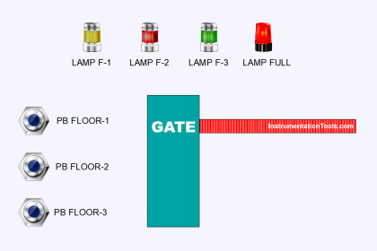
![Multi-Tank Liquid Level Control System with Fill Priority [PLC]](https://instrumentationtools.com/wp-content/uploads/2025/07/Multi-Tank-Liquid-Level-Control-System-with-Fill-Priority-PLC.jpg)
System Sequence
Initialization:
The system starts by measuring the initial level of liquid in each tank.
Tank priority is determined based on the sequence (Tank-1 has the highest priority, Tank-2 has the second priority, and Tank-3 has the lowest priority).
Tank Filling:
If tank-1 has a liquid level below the minimum level, the system will open the valve to tank-1 and activate the pump.
After tank-1 reaches the maximum level, the valve to tank-1 is Closed, and the system continues filling to tank-2 and Tank 3 if necessary.
The pump will turn ON 2 seconds after the valve opens.
Priority Logic:
The tank with the higher priority will be filled first.
If more than one tank is below the minimum level, filling is carried out sequentially according to priority.
Filling Termination:
If all tanks are at a safe level, the system will turn Off the pump and Close all valves.
Alarm Indicator:
Each tank has an indicator alarm during the filling process and when the tank is full.
Multi-Tank Liquid Level Control System
Project IO Details
| S.No. | Comment | Input (I) | Output(Q) | Memory Bit | Memory Word | Timers |
| 1 | PB_START | 0.00 | ||||
| 2 | PB_STOP | 0.01 | ||||
| 3 | VALVE_TANK1 | 100.00 | ||||
| 4 | VALVE_TANK2 | 100.01 | ||||
| 5 | VALVE_TANK3 | 100.02 | ||||
| 6 | PUMP | 100.03 | ||||
| 7 | TANK1_FILL | 100.04 | ||||
| 8 | TANK1_FULL | 100.05 | ||||
| 9 | TANK2_FILL | 100.06 | ||||
| 10 | TANK2_FULL | 100.07 | ||||
| 11 | TANK3_FILL | 101.00 | ||||
| 12 | TANK3_FULL | 101.01 | ||||
| 13 | PV_TANK1 | D0 | ||||
| 14 | PV_TANK2 | D1 | ||||
| 15 | PV_TANK3 | D2 | ||||
| 16 | SYSTEM_ON | W0.00 | ||||
| 17 | TIMER_PUMP | T0000 |
PLC Logic
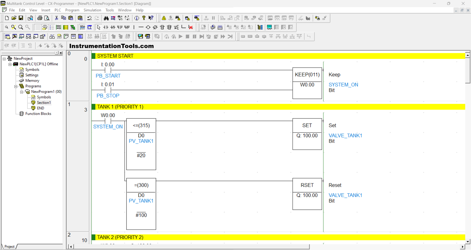
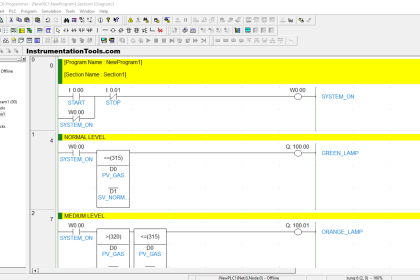
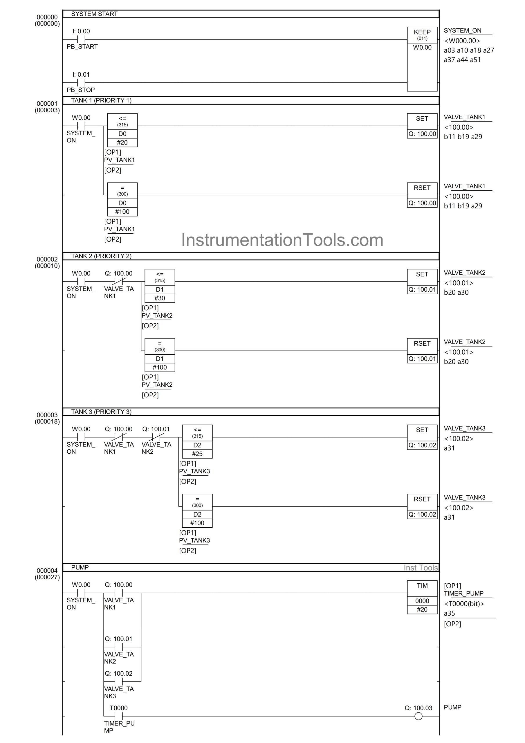
RUNG 0 (SYSTEM ON)
In this Rung, the memory bit SYSTEM_ON (W0.00) will be in the HIGH state when the PB_START (0.00) button is Pressed. Because it uses the KEEP(011) instruction, the memory bit SYSTEM_ON (W0.00) will remain in the HIGH state even though the PB_START (0.00) button has been released.
If the PB_STOP (0.01) button is Pressed, the memory bit SYSTEM_ON (W0.00) will be in the LOW state.
RUNG 1 (TANK 1 (PRIORITY 1))
In this Rung, the output VALVE_TANK1 (100.00) will be OPEN when the NO contact of the memory bit SYSTEM_ON (W0.00) in the HIGH state and the value of the memory word PV_TANK1 (D0) is Less Than Or Equal To “20”.
The VALVE_TANK1 (100.00) output will be CLOSE when the NO contact of the memory bit SYSTEM_ON (W0.00) in the HIGH state and the value of the word memory PV_TANK1 (D0) is Equal To “100”.
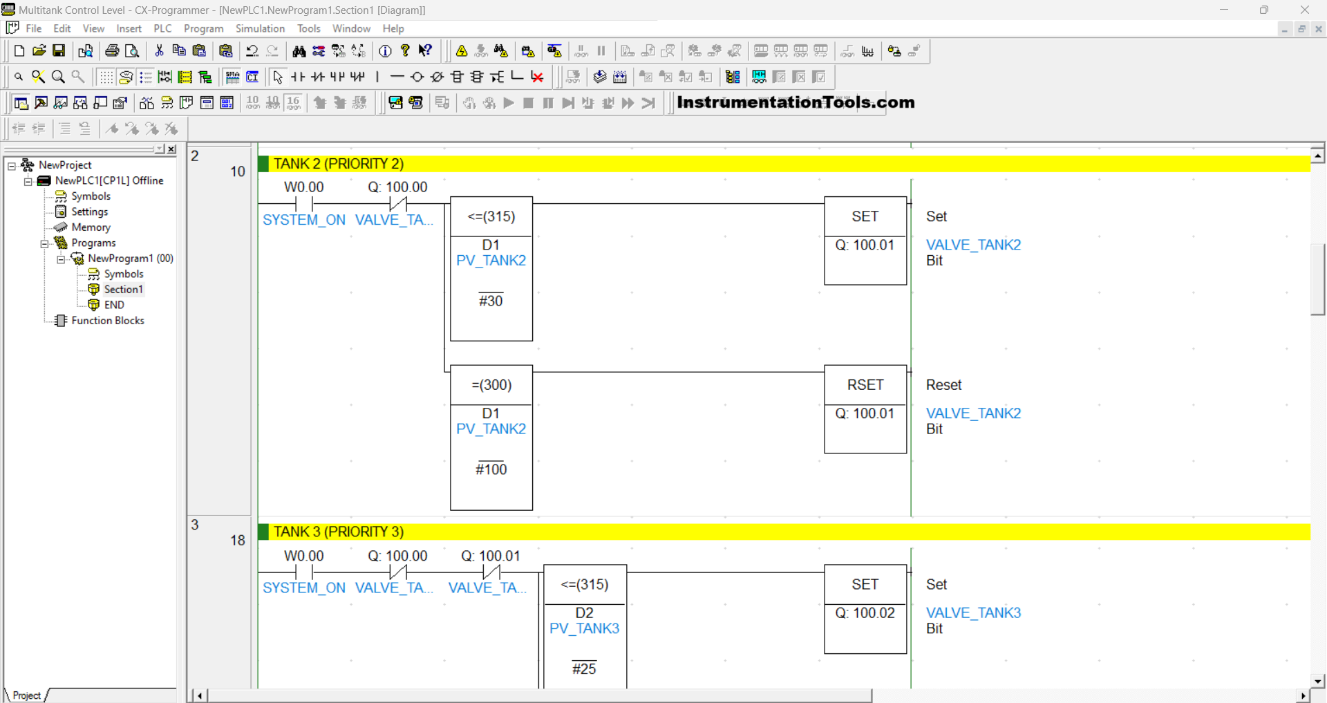
RUNG 2 (TANK 2 (PRIORITY 2))
In this Rung, the output VALVE_TANK2 (100.01) will be OPEN when the NO contact of the memory bit SYSTEM_ON (W0.00) in the HIGH state and the value of the memory word PV_TANK2 (D1) is Less Than Or Equal To “30”.
The VALVE_TANK2 (100.01) output will be CLOSE when the NO contact of the memory bit SYSTEM_ON (W0.00) in the HIGH state and the value of the word memory PV_TANK2 (D1) is Equal To “100” or if the NC contact of the VALVE_TANK1 (100.00) output in the HIGH state.
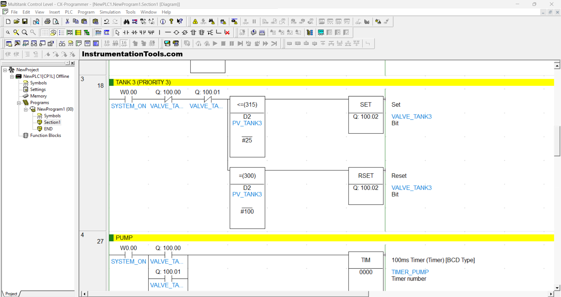
RUNG 3 (TANK 3 (PRIORITY 3))
In this rung, the output VALVE_TANK3 (100.02) will be OPEN when the NO contact of the memory bit SYSTEM_ON (W0.00) in a HIGH state, and the value of the memory word PV_TANK3 (D2) is Less Than Or Equal To “25”.
The output VALVE_TANK3 (100.02) will be CLOSED when the NO contact of the memory bit SYSTEM_ON (W0.00) is in a HIGH state, and the value of the memory word PV_TANK3 (D2) is equal to “100”.
Or, if the NC contact of the VALVE_TANK1 (100.00) or VALVE_TANK2 (100.01) output is in the HIGH state, then the VALVE_TANK3 (100.02) output will be CLOSED.
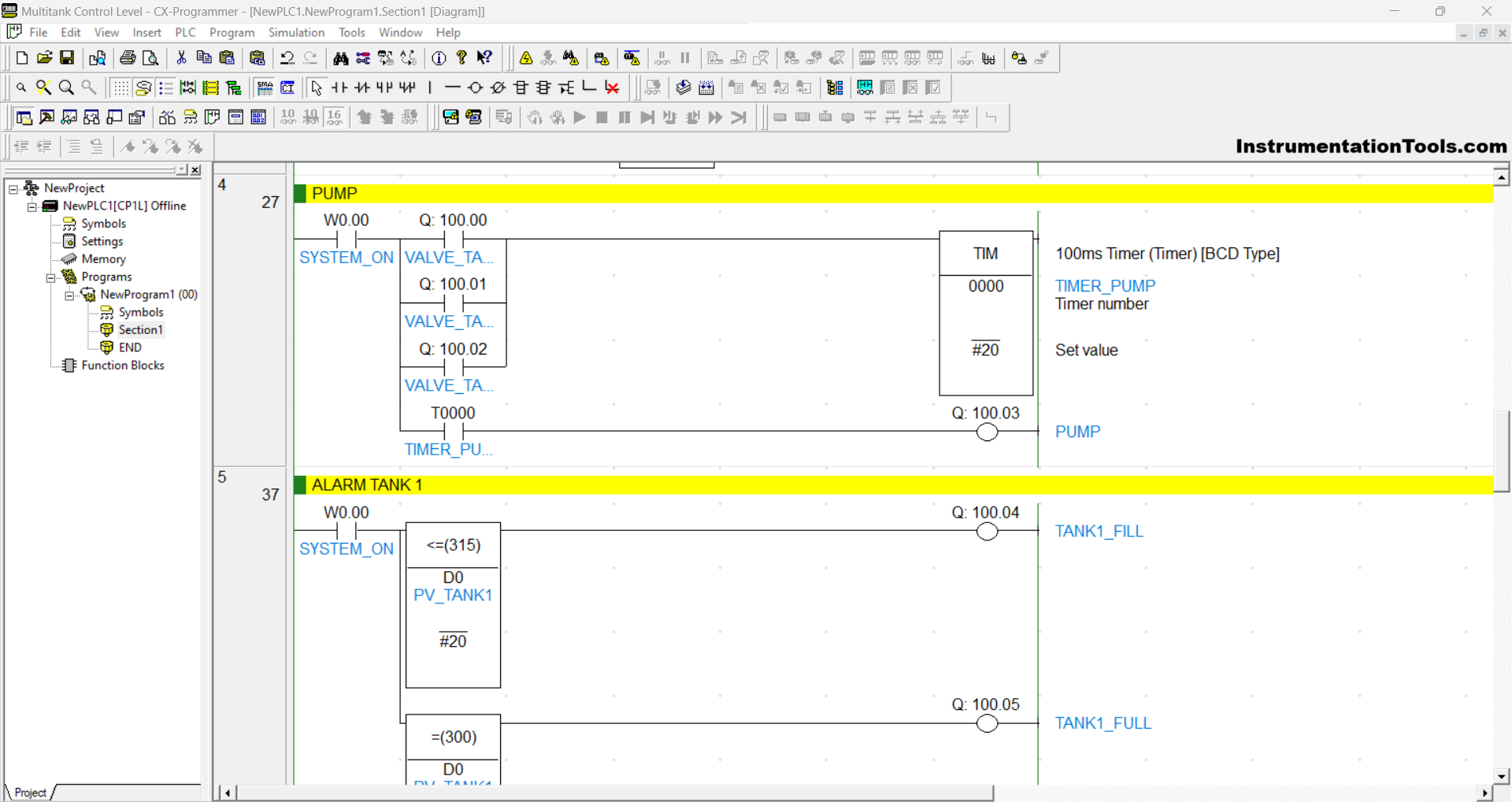
RUNG 4 (PUMP)
When the NO contact of the memory bit SYSTEM_ON (W0.00) in a HIGH state and any one of the NO contacts of the outputs VALVE_TANK1 (100.00), VALVE_TANK3 (100.02), or VALVE_TANK2 (100.01) in a HIGH state, the TIMER_PUMP (T0000) timer will Start counting up to 2 seconds.
The PUMP (100.03) output will turn ON when the NO contact of the TIMER_PUMP (T0000) is in a HIGH state.
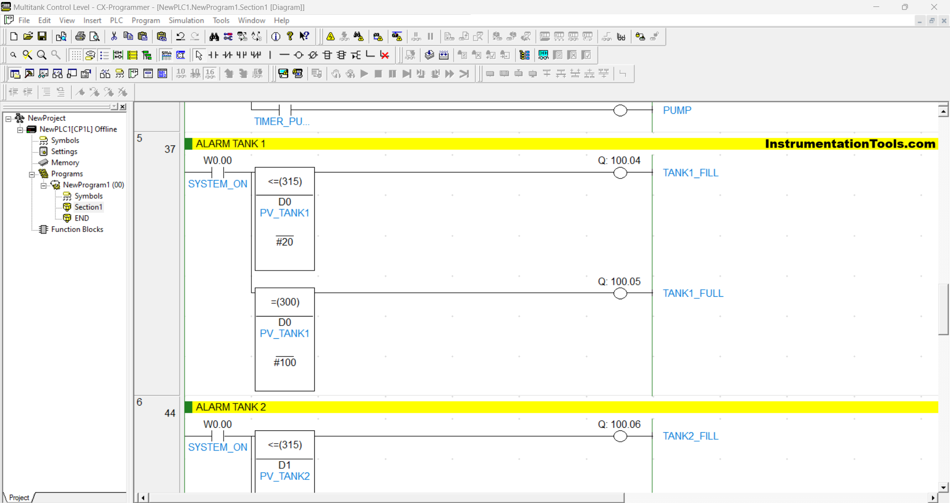
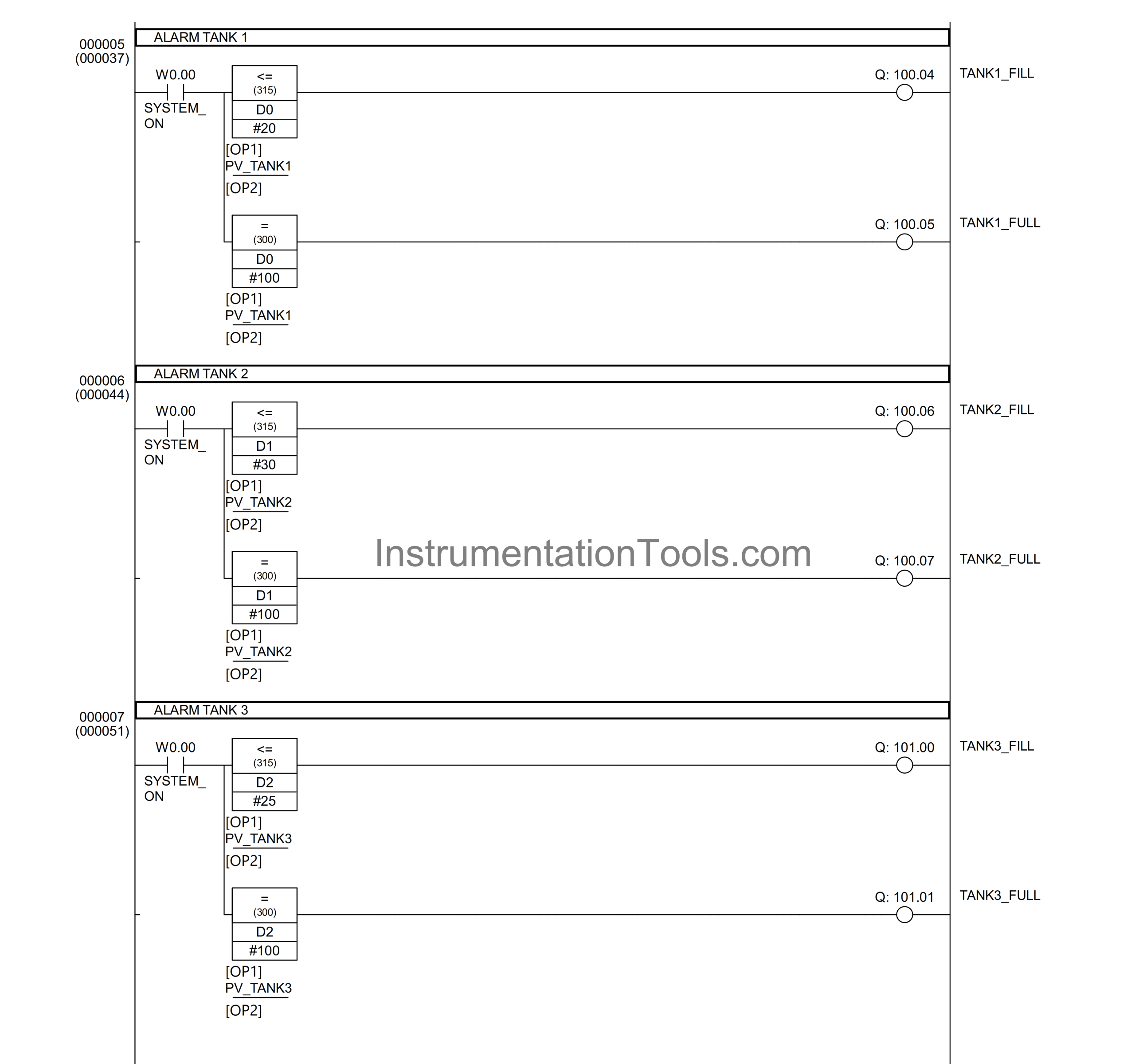
RUNG 5 (TANK ALARM 1)
In this Rung, the output TANK1_FILL (100.04) will be ON when the NO contact of the memory bit SYSTEM_ON (W0.00) in the HIGH state and the value of the memory word PV_TANK1 (D0) is Less Than Or Equal To “20”.
The TANK1_FULL (100.05) output will be ON if the NO contact of the memory bit SYSTEM_ON (W0.00) in the HIGH state and the value of the memory word PV_TANK1 (D0) is Equal To “100”.
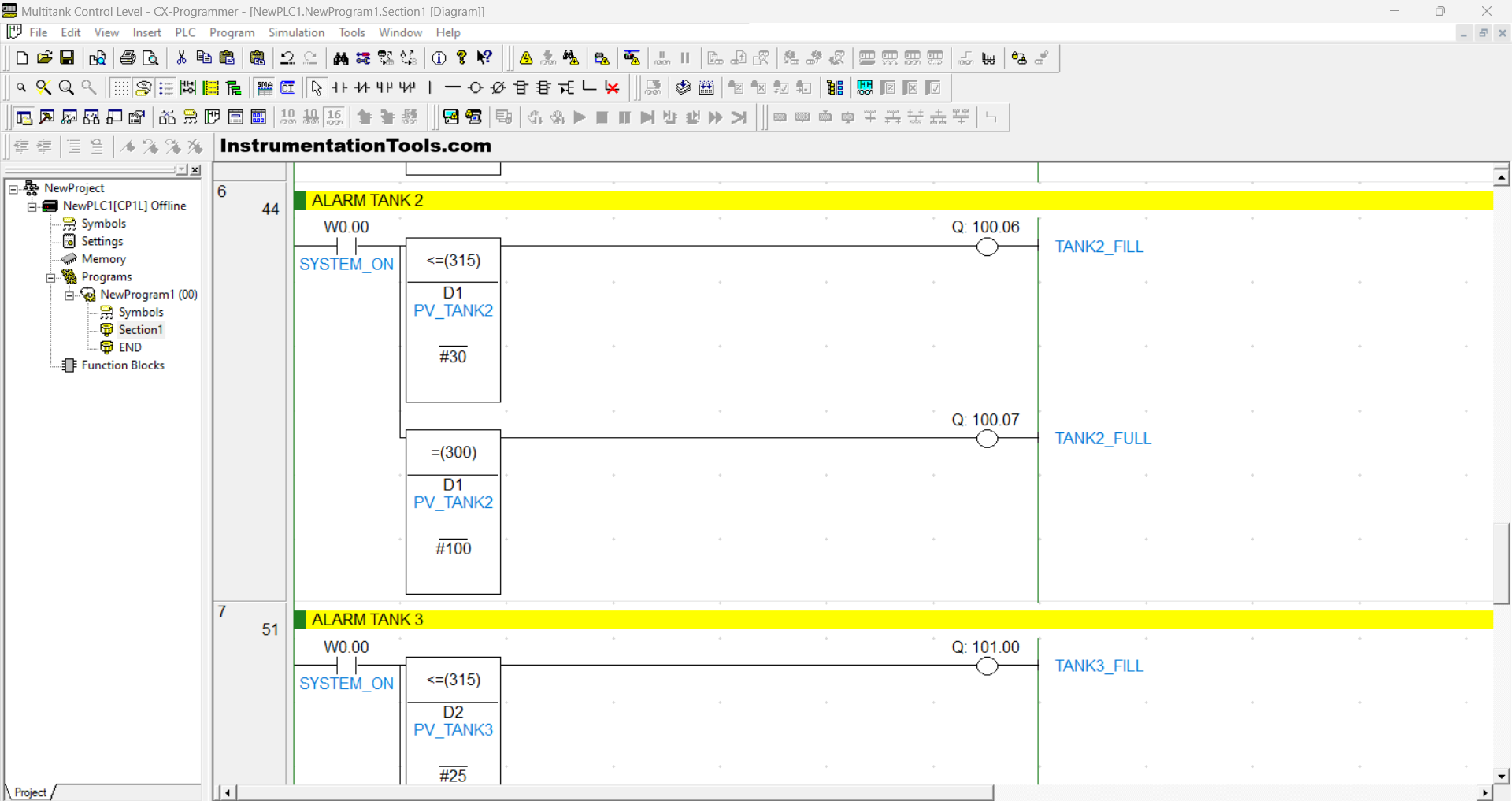
RUNG 6 (TANK ALARM 2)
In this Rung, the output TANK2_FILL (100.06) will be ON when the NO contact of the memory bit SYSTEM_ON (W0.00) in the HIGH state and the value of the memory word PV_TANK2 (D1) is Less Than Or Equal To “30”.
The output TANK2_FULL (100.07) will be ON if the NO contact of the memory bit SYSTEM_ON (W0.00) in the HIGH state and the value of the memory word PV_TANK2 (D1) is Equal To “100”.
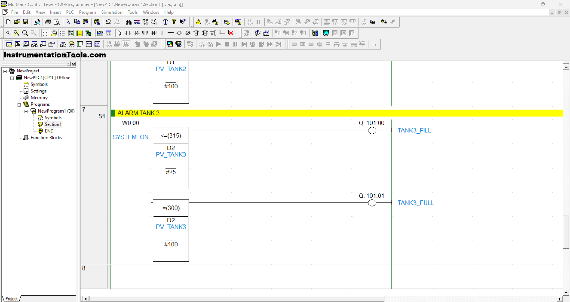
RUNG 7 (TANK ALARM 3)
In this Rung, the output TANK3_FILL (101.00) will be ON when the NO contact of the memory bit SYSTEM_ON (W0.00) in the HIGH state and the value of the memory word PV_TANK3 (D2) is Less Than Or Equal To “25”.
The TANK3_FULL (101.01) output will be ON if the NO contact of the memory bit SYSTEM_ON (W0.00) in the HIGH state and the value of the memory word PV_TANK3 (D2) is Equal To “100”.
Read Next:
- Studio 5000: Programming Three Motors
- Two Hand Press Safety Control Circuit
- Simple Conveyor Control PLC Programming
- PLC Interlock Logic with First Input Priority
- PLC Programming for Weight-Based Packaging