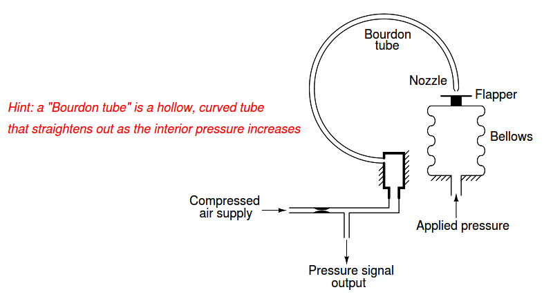
Explain how each of the following pressure instruments works, identifying whether each one uses the principle of motion-balance or the principle of force-balance.
Motion-Balance and Force-Balance
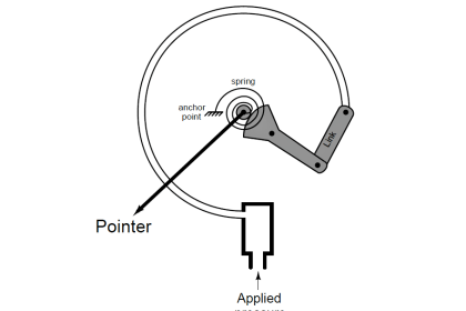
Please note that a series of angled lines projecting from a vertical or horizontal line represents a point of anchoring, where that horizontal or vertical surface is stationary:
Example 1:
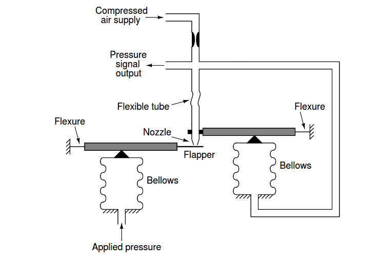
Example 2:
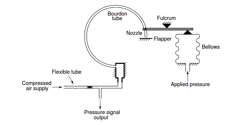
Example 3:
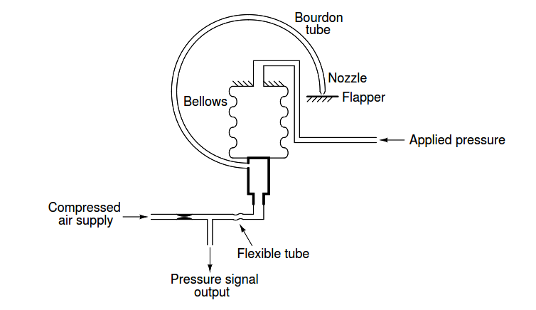
Example 4:
Example 5:
Example 6:
Example 7:
Example 8:
Example 9:
Answer:
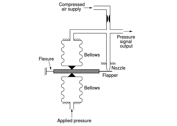
Example 1: Force-balance
Example 2: Motion-balance
Example 3: Force-balance
Example 4: Force-balance
Example 5: Motion-balance
Example 6: Motion-balance
Example 7: Force-balance
Example 8: Motion-balance
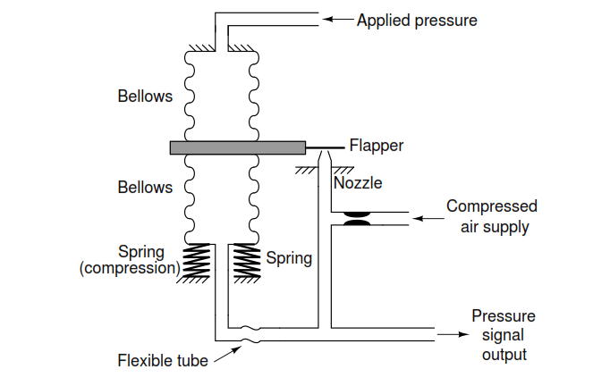
Example 9: Force-balance
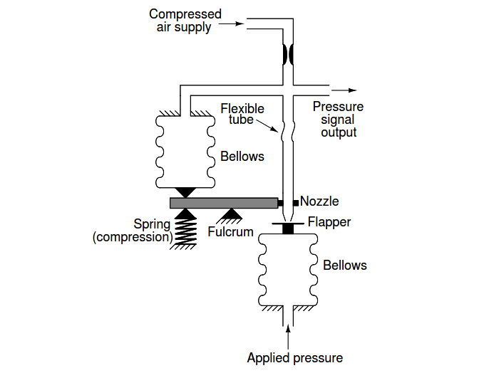
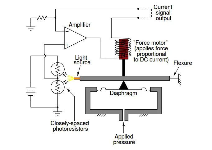
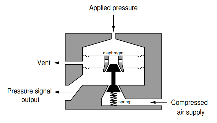
The general principle to keep in mind here is that motion-balance instruments generate a motion to counteract an input motion in order to maintain a constant detector (flapper/nozzle) gap, while force-balance instruments generate a force to counteract an input force in order to maintain a constant detector (flapper/nozzle) gap.
Example number 9 is tricky because one might argue it is motion-balance by virtue of the lower bellows’ stretching motion as output pressure increases.
However, the fact that the two bellows’ forces oppose each other to ensure the flapper remains stationary in order to hold a constant flapper/nozzle gap is a defining characteristic of any force-balance mechanism.
Also, the degree of spring stiffness has no effect whatsoever on the gain of this mechanism, which it would if it were motion-balance (i.e. if the amount of motion generated per unit increase in output pressure were related at all to the amount of input pressure increase).
The two bellows’ forces will cancel each other to achieve equilibrium regardless of how much or how little the spring must compress in the process of achieving that balance. If this were a true motion-balance mechanism, weakening the spring (making it less stiff) would result in a decrease of output pressure because less pressure would be required to move as far as before.
Here, a weakened spring would indeed result in the lower bellows expanding a greater distance than before to balance the same amount of input pressure, but this would actually be the same output pressure as before, meaning the change in required motion has no effect on the gain.
Interest to add any further points? Share your answers with us through the below comments section.
Read Next:
- Thermocouple Details
- Ultrasonic Sensors Work
- Baffle Nozzle Question
- Pneumatic Repeater
- Threads Standard
Credits: Tony R. Kuphaldt


This tutorial is interesting and informative. I will like to continue with learning.