This article discusses the use of timer instructions in the GX Works2 software of Mitsubishi PLC with a ladder diagram. A timer is an instruction used to control the timing of a process operation, such as delaying the activation or deactivation of a device (output) based on a specified time interval. The timer functions by counting time according to a preset value. GX Works2 provides four types of timers with different time resolutions: 100 ms, 10 ms, and retentive types with 100 ms and 1 ms intervals. To understand how each timer works, they will be tested by activating a lamp based on a specific preset time.
Program Objectives
100 ms Timer Instruction
The 100 ms timer instruction with a time interval speed of 0.1 seconds (100 ms) and does not retain time data. This instruction has only one input parameter to activate the timer, and it will deactivate if it does not receive a trigger. This timer can be used with memory addresses T0 to T199. It is an up-counting timer.
10 ms Timer Instruction
The 10 ms timer has a time interval speed of 0.01 seconds (10 ms) and does not retain time data. This instruction also has only one input parameter to activate the timer, and it will deactivate if it does not receive a trigger. It can be used with memory addresses T200 to T245. It is an up-counting timer.
For testing purposes, in this program, both the 100 ms and 10 ms timer instructions will be activated by the same button with the same adjustable preset time.
Each timer will control a different output.
Retentive 100 ms Timer Instruction
The retentive 100 ms timer has a time interval speed of 0.1 seconds (100 ms) and is capable of retaining time data. It has only one input parameter to activate the timer and requires the “RST” instruction to reset the stored time data. This timer can be used with memory addresses T250 to T156. It is an up-counting timer.
Retentive 1 ms Timer Instruction
The retentive 1 ms is a timer instruction with a time interval speed of 0.001 seconds (1 ms) and is capable of retaining time history data. It has only one input parameter to activate the timer and requires the “RST” instruction to reset the stored time data. It can be used with memory addresses T246 to T249.
It is an up-counting timer.
For testing purposes, in this program, both the Retentive 100 ms and Retentive 1 ms timer instructions will be activated using the same button with the same adjustable preset time.
Each timer will control a different output.
*Note:
In this simulation video, there is a minor bug where the 100 ms timer instruction (T0) runs at a speed of 1 second, whereas it should run at a speed of 0.1 second. This is caused by a built-in bug in the PLC hardware that I use, which is the FX3U LOLLETE PLC (not a program error). However, when the program is run in simulation mode using GX Works2, the timer can function according to the 100 ms speed.
Simulation Video
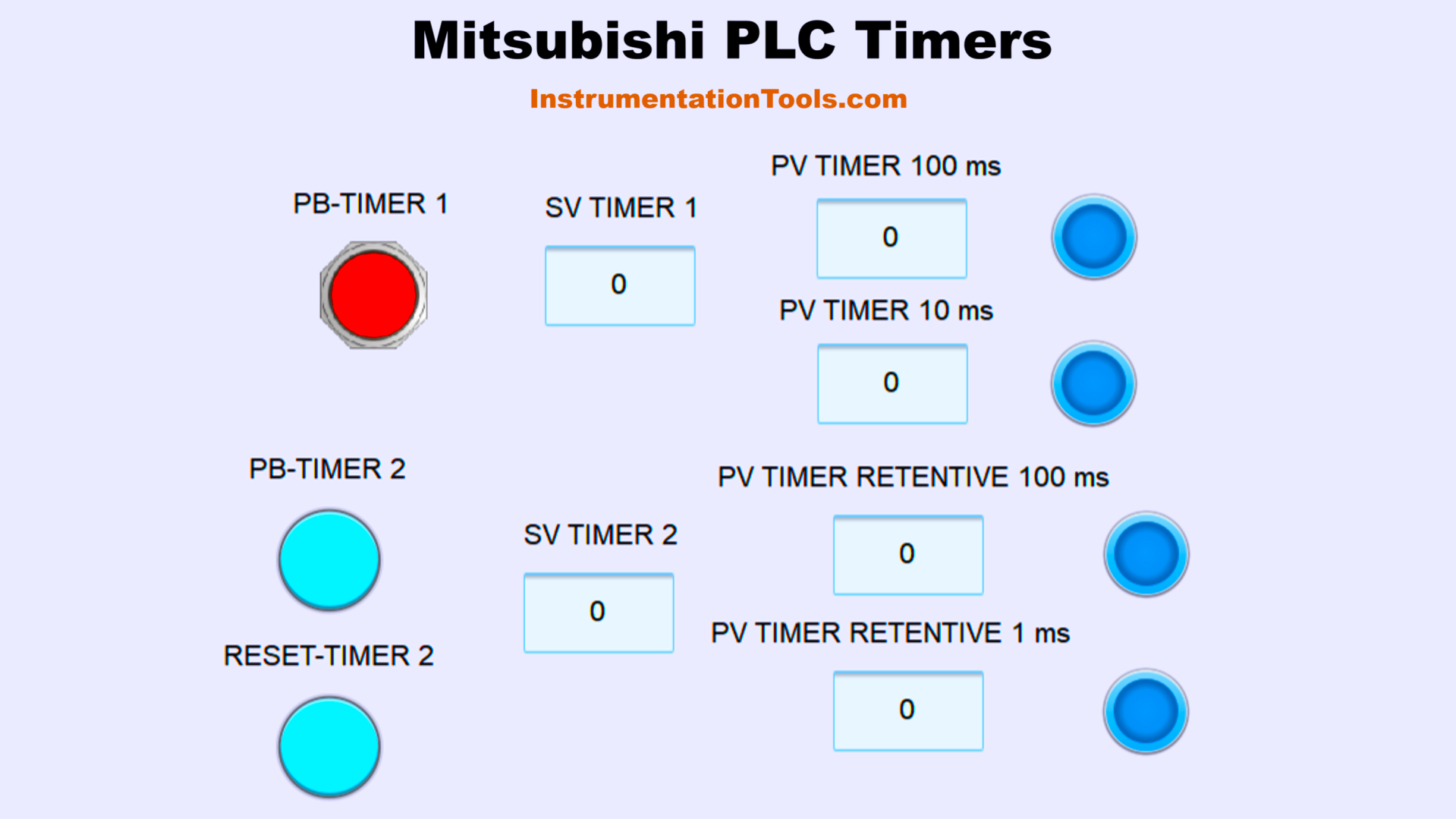
Timers in Mitsubishi PLC Programming
IO Mapping Details
| S.No. | Comment | Input (I) | Output(Q) | Timer | Memory Word |
|---|---|---|---|---|---|
| 1 | TRIGGER_TIMER1 | M0 | |||
| 2 | TRIGGER_TIMER2 | M1 | |||
| 3 | TRIGGER_RST | M2 | |||
| 4 | OUT1 | Y000 | |||
| 5 | OUT2 | Y001 | |||
| 6 | OUT4 | Y003 | |||
| 7 | OUT5 | Y004 | |||
| 8 | TIMER_100ms | T0 | |||
| 9 | TIMER_10ms | T200 | |||
| 10 | TIMER_RET_100ms | T250 | |||
| 11 | TIMER_RET_1ms | T246 | |||
| 12 | SV_TIMER1 | D0 | |||
| 13 | SV_TIMER2 | D1 |
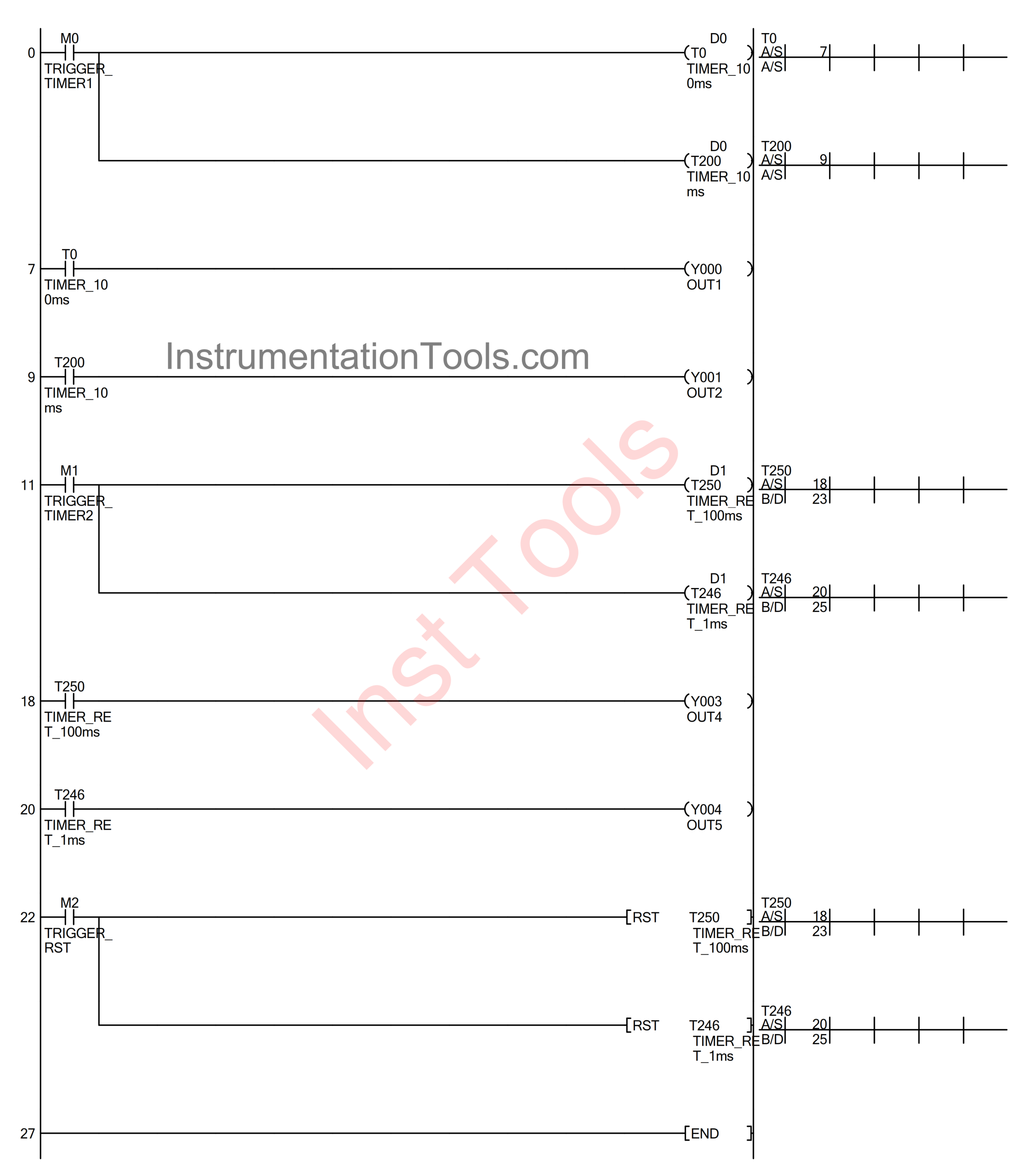
Programming of PLC Code
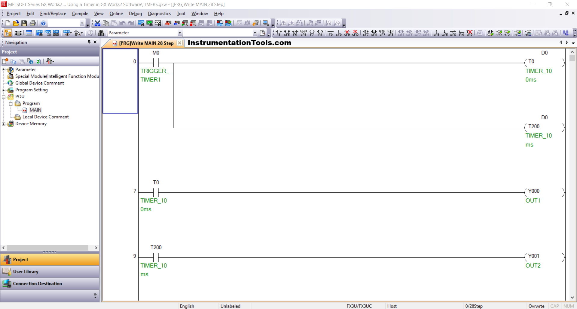
RUNG 0
In this Rung, if the TRIGGER_TIMER1 (M0) button is pressed, then the TIMER_100ms (T0) and TIMER_10ms (T200) timer instructions will start counting up according to the value set in the SV_TIMER1 (D0) memory word and when it has finished counting, the TIMER_100ms (T0) and TIMER_10ms (T200) timer instructions will be ON.
The TIMER_100ms (T0) and TIMER_10ms (200) timer instructions will be OFF if the TRIGGER_TIMER1 (M0) button has been released.
RUNG 7
In this Rung, the OUT1 (Y0) output will be ON if the NO contact of TIMER_100ms (T0) is in the HIGH state.
RUNG 9
In this Rung, the output OUT2 (Y1) will be ON if the NO contact of TIMER_10ms (200) is in the HIGH state.
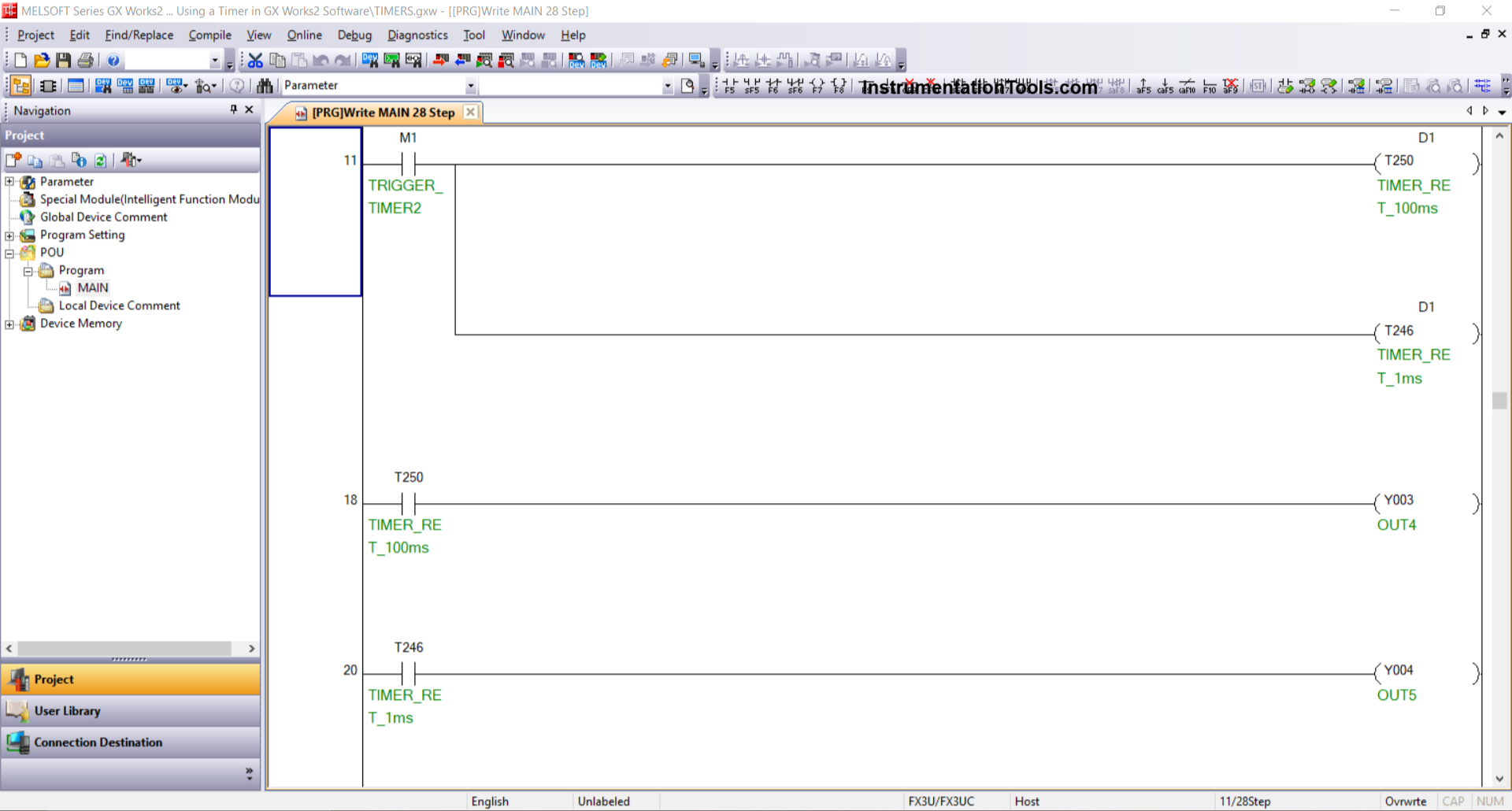
RUNG 11
In this Rung, if the TRIGGER_TIMER2 (M1) button is pressed, then the TIMER_RET_100ms (T250) and TIMER_RET_1ms (T246) timer instructions will start counting up according to the value set in the SV_TIMER2 (D1) memory word. When the counting is finished, the TIMER_RET_100ms (T250) and TIMER_RET_1ms (T246) timer instructions will be ON.
The TIMER_RET_100ms (T250) and TIMER_RET_1ms (T246) timer instructions will be OFF if the TRIGGER_TIMER2 (M1) button has been released.
RUNG 18
In this Rung, the OUT4 (Y3) output will be ON if the NO contact of TIMER_RET_100ms (T250) is in the HIGH state.
RUNG 20
In this Rung, output OUT5 (Y4) will be ON if the NO contact of TIMER_RET_1ms (T246) is in the HIGH state.
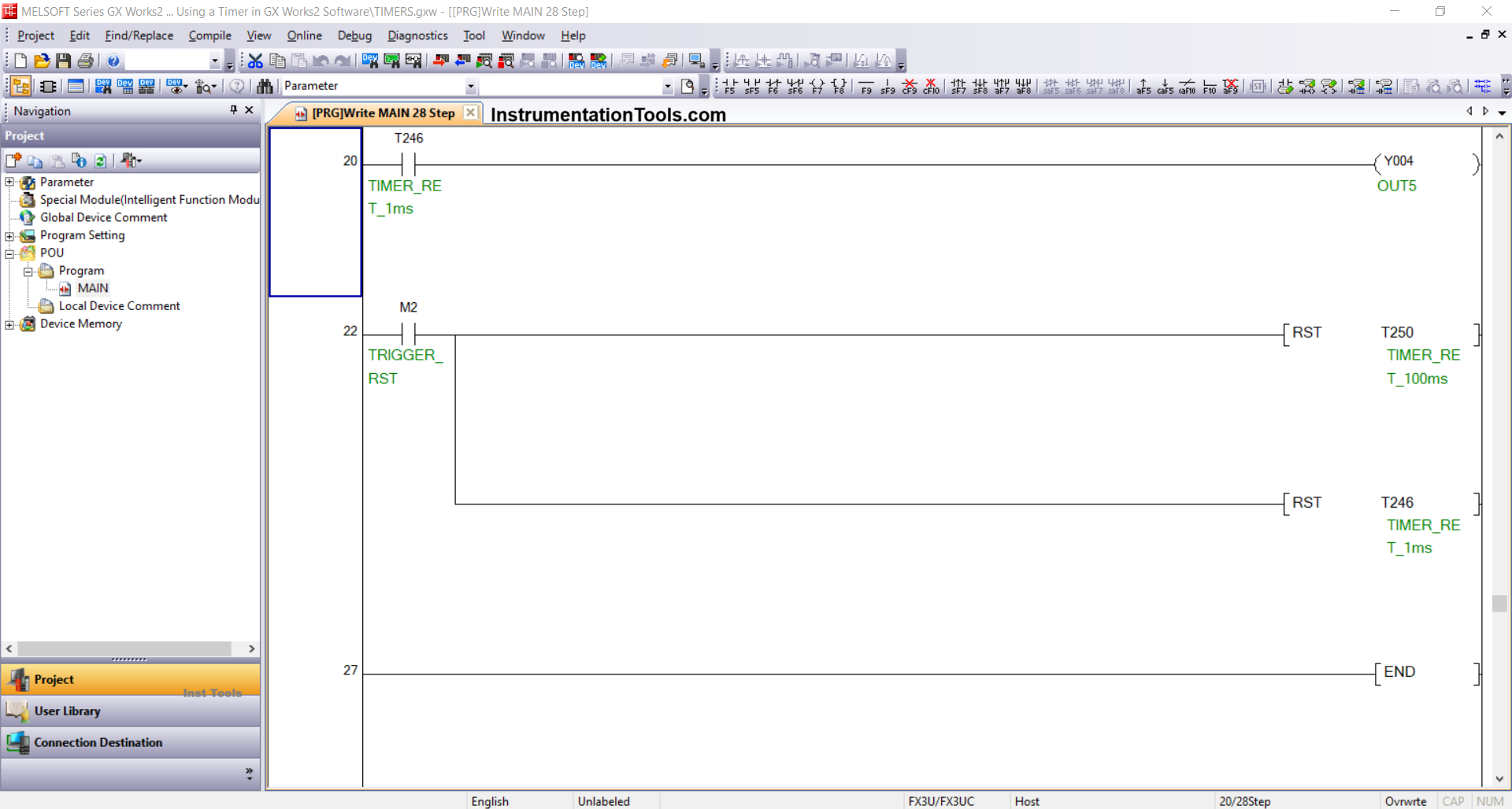
RUNG 22
In this Rung, if the TRIGGER_RST (M2) button is pressed, then the timer instructions TIMER_RET_100ms (T250) and TIMER_RET_1ms (T246) will be OFF, and the PV time data is reset to zero “0”.
Read Next:
- PLC Parking Information Systems STL Program
- PLC Weighing with Labeling Programming
- PLC Programming of Clothes Washing System
- PLC Example Programming for Star-Delta System
- Programming PLC Manual Sequential Machine