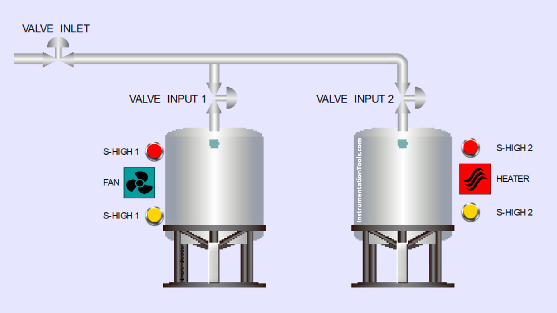
This article discusses the design of an automatic filling system for the dual tanks process using Mitsubishi PLC ladder logic. The system is designed to supply hot and cold water in each respective tank. Heating and cooling processes will only take place when both tanks are filled. Conversely, these processes will automatically stop if there is no water in either tank.
Program Objective
System Steps:
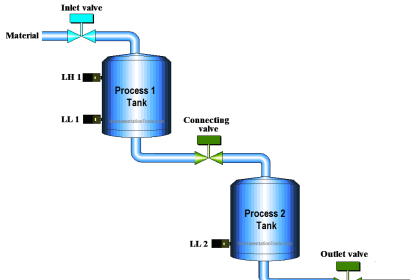
1. Parallel Tank System
- Two tanks (1 & 2) are connected to the same water source.
- Each tank has its own input valve.
- The main inlet valve opens when the system is activated.
2. Tank Functions
- Tank 1: Cold water.
- Tank 2: Hot water.
3. Automatic Filling
- If the water level is below the minimum, the input valve opens.
- Filling stops once the maximum level is reached.
4. Heater & Cooler Activation
- When tanks are full:
- Tank 2 → Heater is activated.
- Tank 1 → Cooling fan is activated.
5. Operating Conditions
- Heater and fan only operate if the tanks contain water.
Dual Tank Process
IO Mapping
| S.No. | Comment | Input (I) | Output (Q) | Memory Bit |
|---|---|---|---|---|
| 1 | START | M0 | ||
| 2 | STOP | M1 | ||
| 3 | SENS_LOW_TANK1 | M3 | ||
| 4 | SENS_HIGH_TANK1 | M4 | ||
| 5 | SENS_LOW_TANK2 | M5 | ||
| 6 | SENS_HIGH_TANK2 | M6 | ||
| 7 | VALVE_INLET | Y000 | ||
| 8 | VALVE_IN_TANK1 | Y001 | ||
| 9 | EXHAUST_FAN | Y002 | ||
| 10 | VALVE_IN_TANK2 | Y003 | ||
| 11 | HEATER | Y004 | ||
| 12 | SYSTEM_ON | M2 |
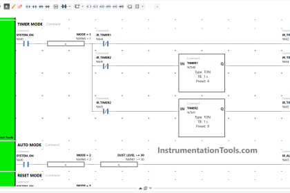
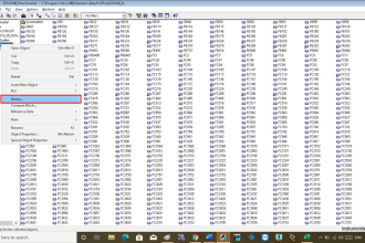
Mitsubishi PLC Ladder Logic
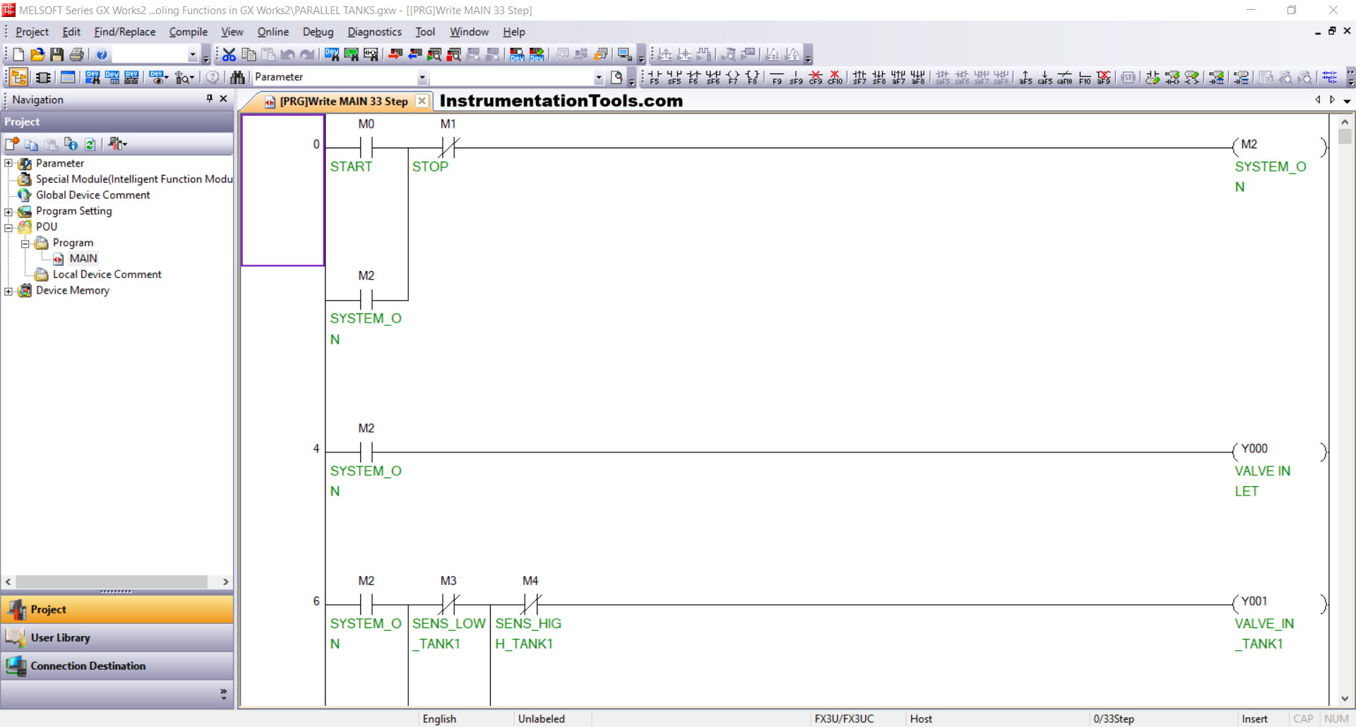
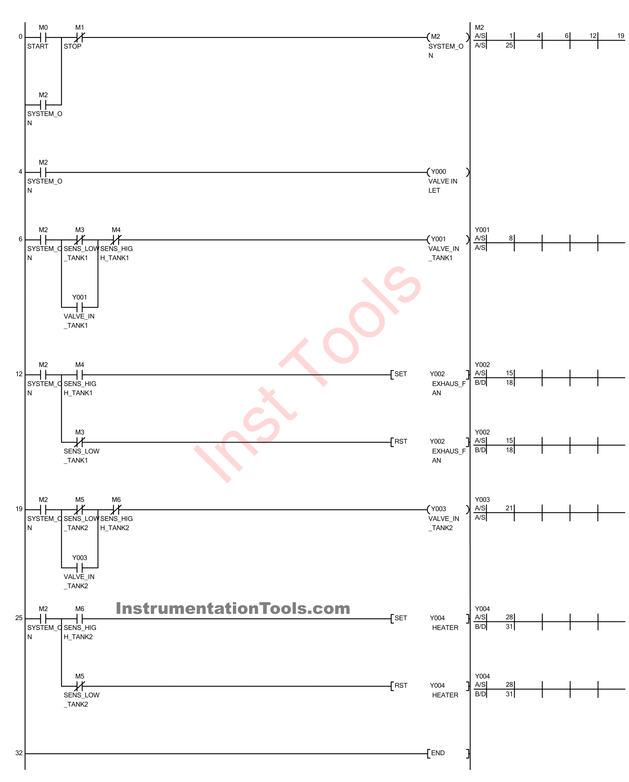
RUNG 0
In this Rung, the memory bit SYSTEM_ON (M2) will be in a HIGH state if the START (M0) button is pressed. Even though the START (M0) button has been released, the memory bit SYSTEM_ON (M2) will remain in a HIGH state, because it uses Latching.
If the STOP (M1) button is pressed, the memory bit SYSTEM_ON (M2) will be in a LOW state.
RUNG 4
In this Rung, the VALVE_INLET (Y000) output will be OPEN if the NO contact of the memory bit SYSTEM_ON (M2) is in a HIGH state.
If the NO contact of the memory bit SYSTEM_ON (M2) is in a LOW state, the VALVE_INLET (Y000) output will be CLOSED.
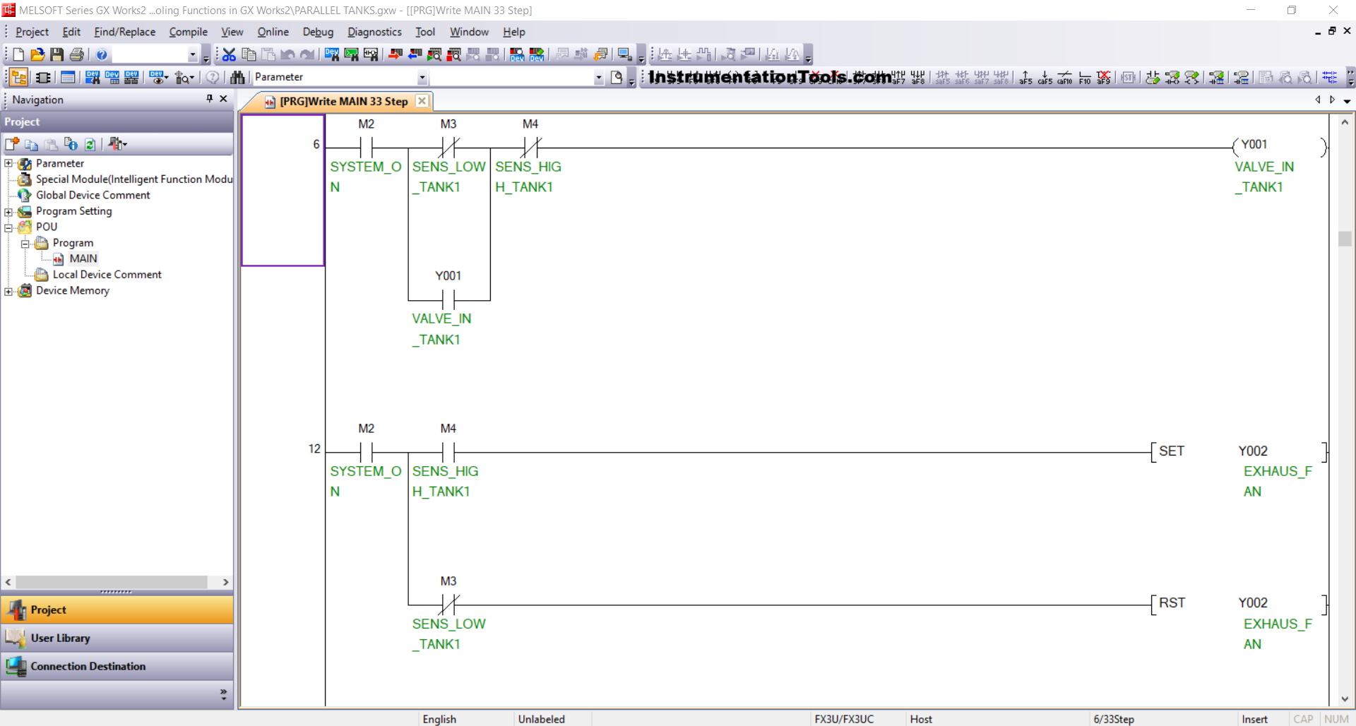
RUNG 6
When the NO contact of the memory bit SYSTEM_ON (M2) is in the HIGH state and the NC contact of the SENS_LOW_TANK1 (M3) and SENS_HIGH_TANK1 (M4) sensors are in the LOW state, the VALVE_IN_TANK1 (Y001) output will be OPEN.
The VALVE_IN_TANK1 (Y001) output will remain OPEN even though the NC contact of the SENS_LOW_TANK1 (M3) sensor is in the HIGH state. Because it uses Latching.
When the NC contact of the SENS_HIGH_TANK 1(M4) sensor is in the HIGH state, the VALVE_IN_TANK1 (Y001) output will be CLOSED.
RUNG 12
In this Rung, if the NO contact of the memory bit SYSTEM_ON (M2) and the SENS_HIGH_TANK1 (M4) sensor, and the NC contact of the SENS_LOW_TANK1 (M3) sensor are in the HIGH state, then the EXHAUST_FAN (Y002) output will be ON.
When the NO contact of the SENS_HIGH_TANK1 (M4) sensor and the NC contact of the SENS_LOW_TANK1 (M3) sensor are in the LOW state, then the EXHAUST_FAN (Y002) output will be OFF.
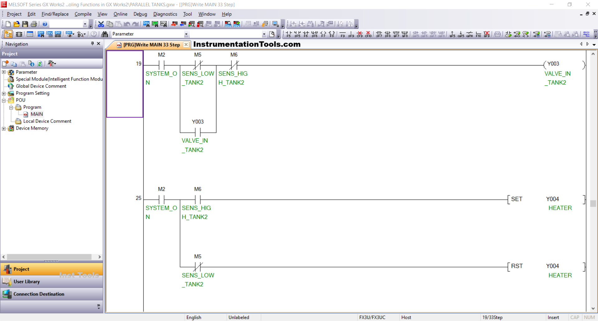
RUNG 19
The output VALVE_IN_TANK2 (Y003) will be OPEN when the NO contact of the memory bit SYSTEM_ON (M2) is in the HIGH state and the NC contacts of the SENS_LOW_TANK2 (M5) and SENS_HIGH_TANK2 (M6) sensors are in the LOW state.
Although the NC contact of the SENS_LOW_TANK2 (M5) sensor is in the HIGH state, the output VALVE_IN_TANK2 (Y003) will remain OPEN. Because it uses Latching.
When the NC contact of the SENS_HIGH_TANK2 (M6) sensor is in the HIGH state, the output VALVE_IN_TANK2 (Y003) will be CLOSED.
RUNG 25
In this Rung, if the NO contact of the memory bit SYSTEM_ON (M2) and the SENS_HIGH_TANK2 (M6) sensor, and the NC contact of the SENS_LOW_TANK2 (M5) sensor are in the HIGH state, then the HEATER (Y004) output will be ON.
When the NO contact of the SENS_HIGH_TANK2 (M6) sensor and the NC contact of the SENS_LOW_TANK2 (M5) sensor are in the LOW state, then the HEATER (Y004) output will be OFF.
Read Next:
- Waste-Burning System OMRON PLC Programming
- PLC Example on Manufacturing Line Assembly
- Analog Alarms using PLC Functional Block Diagram
- Example Logic for Perfume Mixing and Filling System
- Machine Indicator Lights PLC Programming Example