In this article, you will find the medium-level PLC exercise for students in automation to improve your programming skills.
Create a PLC program for automatic perfume mixing and filling with Ecostruxure machine expert-basic software of Schneider Electric PLC.
Medium-Level PLC Exercise
The PLC system uses 2 buttons, the START_SYSTEM (I0.0) button is used to Turn On the system and the STOP_SYSTEM (I0.1) button is used to Turn Off the system. This system also has 3 sensors which are used to detect VAT Perfume. The sensor will change to a HIGH state when it detects VAT Perfume.
When the START_SYSTEM (I0.0) button is Pressed, the Liquid Filling process Starts and the Output VALVE_INPUT_PARFUME (Q0.0) will OPEN. The Liquid Filling process will Stop when the Mixer tank is filled with 200kg.
When the VALVE_INPUT_PARFUME (Q0.0) Output is CLOSED, the Liquid Mixing process will be carried out and the MIXER (Q0.1) Output will be ON for 15 seconds. When the Mixing Liquid process is complete, the system will be in Standby Mode.
The VALVE_OUTPUT_PARFUME1 (Q0.2) Output will OPEN for 5 seconds to drain liquid into the VAT Parfume when the VAT_SENSOR1 (I0.2) sensor is HIGH.
The VALVE_OUTPUT_PARFUME2 (Q0.3) Output will OPEN for 5 seconds to drain liquid into the VAT Parfume when the VAT_SENSOR2 (I0.3) sensor is HIGH.
The VALVE_OUTPUT_PARFUME3 (Q0.4) Output will OPEN for 5 seconds to drain liquid into the VAT Parfume when the VAT_SENSOR3 (I0.4) sensor is HIGH.
When the liquid in the Mixer tank is empty, the system will turn OFF.
Inputs and Outputs
| Comment | Input (I) | Output (Q) | Memory Bits | Memory Word | Timers |
| START_SYSTEM | I0.0 | ||||
| STOP_SYSTEM | I0.1 | ||||
| VAT_SENSOR1 | I0.2 | ||||
| VAT_SENSOR2 | I0.3 | ||||
| VAT_SENSOR3 | I0.4 | ||||
| VALVE_INPUT_PARFUME | Q0.0 | ||||
| MIXER | Q0.1 | ||||
| VALVE_OUTPUT_PARFUME1 | Q0.2 | ||||
| VALVE_OUTPUT_PARFUME2 | Q0.3 | ||||
| VALVE_OUTPUT_PARFUME3 | Q0.4 | ||||
| TIMER1 | TM0 | ||||
| TIMER2 | TM1 | ||||
| TIMER3 | TM2 | ||||
| TIMER4 | TM3 | ||||
| SYSTEM_ON | M0 | ||||
| STANDBY_MODE | M1 | ||||
| SYSTEM_OFF | M2 | ||||
| IR_TIMER1 | M3 | ||||
| IR_TIMER2 | M4 | ||||
| IR_TIMER3 | M5 | ||||
| IR_TIMER4 | M6 | ||||
| PARFUME_WEIGHT | MW0 |
PLC Programming
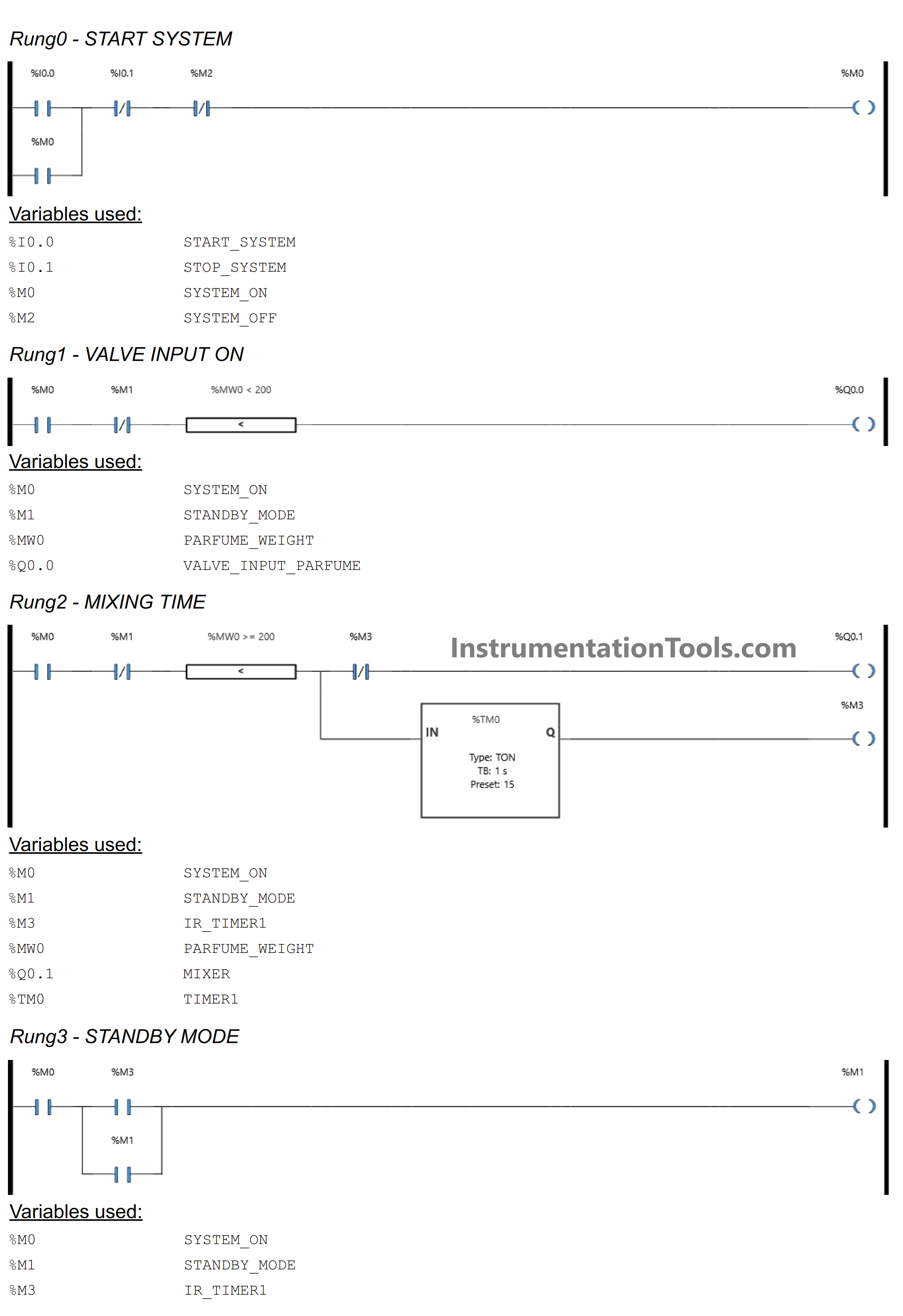
RUNG 0 (START_SYSTEM)
In this Rung, the memory bit SYSTEM_ON (M0) will change to a HIGH state when the START_SYSTEM (I0.0) button is Pressed. The memory bit SYSTEM_ON (M0) remains in the HIGH state even though the START_SYSTEM (I0.0) button has been Released because it uses Latching.
When the STOP_SYSTEM (I0.1) button is Pressed or when the NC contact of memory bit SYSTEM_OFF (M2) is in the HIGH state, the memory bit SYSTEM_ON (M0) will change to the LOW state.
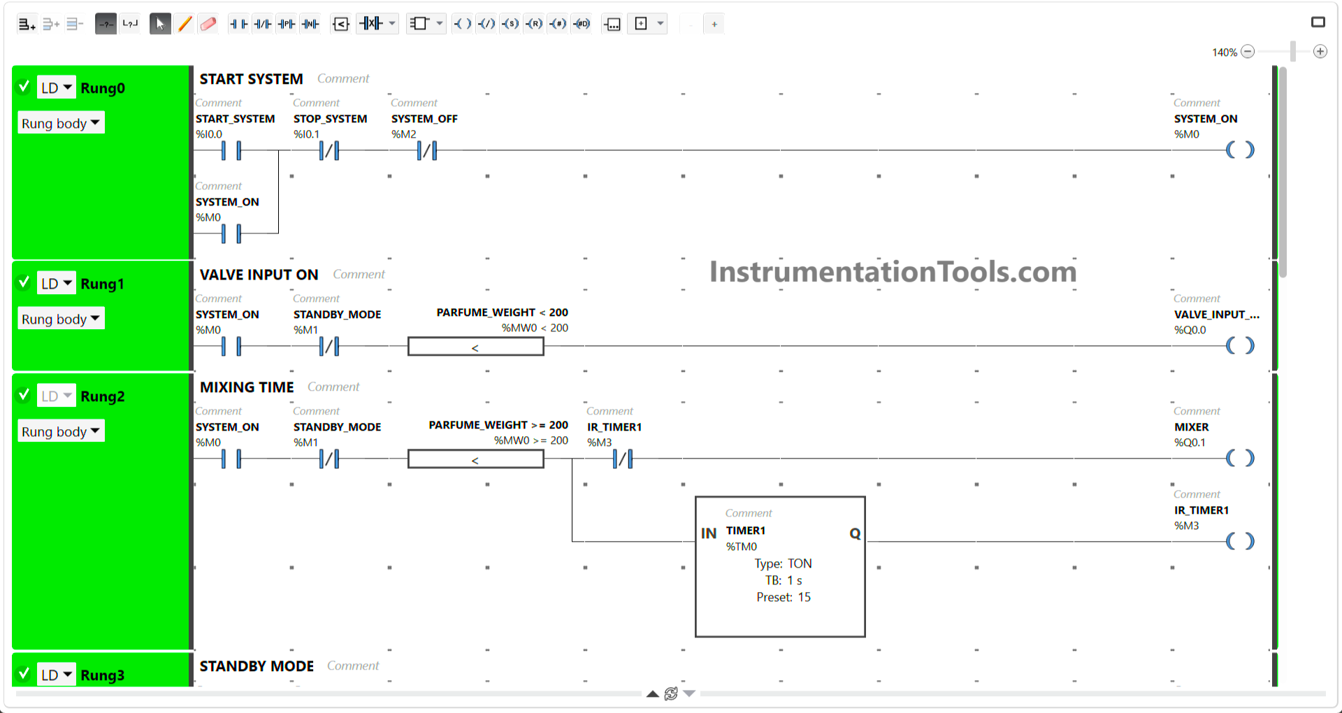
RUNG 1 (VALVE INPUT ON)
In this Rung, when the NO contact of memory bit SYSTEM_ON (M0) in HIGH state and the value in memory word PARFUME_WEIGHT (MW0) is less than “200”, then the Output VALVE_INPUT_PARFUME (Q0.0) will be OPEN.
RUNG 2 (MIXING TIME)
The MIXER (Q0.1) Output will be ON when the NO contact of memory bit SYSTEM_ON (M0) in HIGH state and the value in memory word PARFUME_WEIGHT (MW0) is greater than or equal to “200”. Timer TIMER1 (TM0) will count up to 15 seconds.
When Timer TIMER1 (TM0) finishes counting, the memory bit IR_TIMER1 (M3) changes to a HIGH state.
The MIXER (Q0.1) Output will be OFF when the NC contacts of memory bit SYSTEM_OFF (M2) and the memory bit IR_TIMER1 (M3) are in the HIGH state.
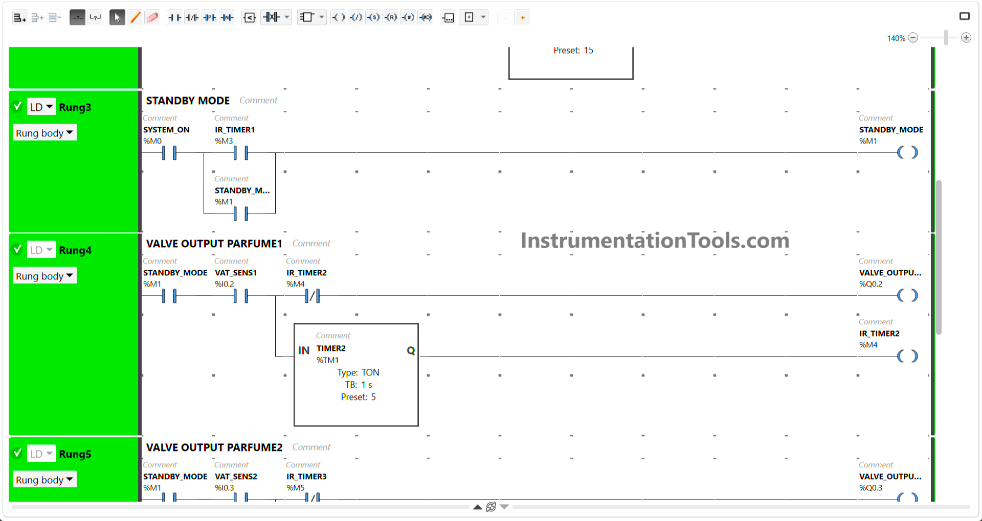
RUNG 3 (STANDBY MODE)
The memory bit STANDBY_MODE (M1) will change to a HIGH state when the NO contacts of memory bit SYSTEM_ON (M0) and IR_TIMER1 (M3) are in the HIGH state.
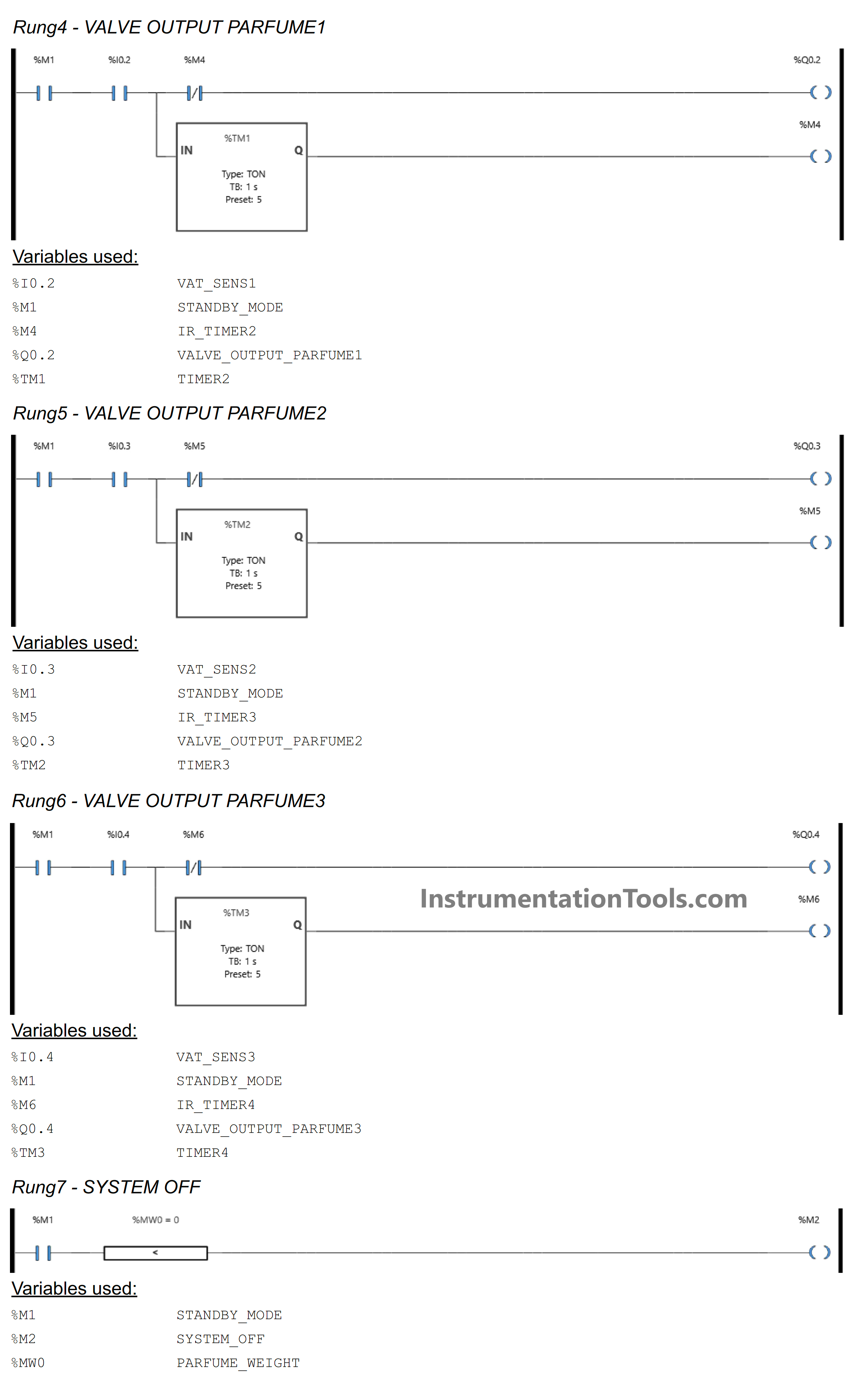
RUNG 4 (PARFUME OUTPUT VALVE1)
The VALVE_OUTPUT_PARFUME1 (Q0.2) Output will be OPEN when the NO contact of memory bit STANDBY_MODE (M1) and the VAT_SENSOR1 (I0.2) sensor in the HIGH state. The timer TIMER2 (TM1) will count up to 5 seconds. When the timer TIMER2 (TM1) finishes counting, the memory bit IR_TIMER2 (M4) will change to HIGH state.
The VALVE_OUTPUT_PARFUME1 (Q0.2) Output will be CLOSE when NO contact of the VAT_SENSOR1 (I0.2) sensor in the LOW state or when the NC contact of memory bit IR_TIMER2 (M4) in the HIGH state.
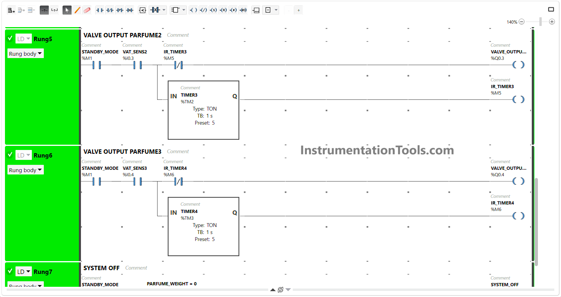
RUNG 5 (PARFUME OUTPUT VALVE2)
The VALVE_OUTPUT_PARFUME2 (Q0.3) Output will be OPEN when the NO contact of memory bit STANDBY_MODE (M1) and the VAT_SENSOR2 (I0.3) sensor in the HIGH state. The timer TIMER3 (TM2) will count for up to 5 seconds. When the timer TIMER3 (TM2) finishes counting, the memory bit IR_TIMER3 (M5) will change to the HIGH state.
The VALVE_OUTPUT_PARFUME2 (Q0.3) Output will be CLOSE when the NO contact of the VAT_SENSOR2 (I0.3) sensor in the LOW state or when the NC contact of memory bit IR_TIMER3 (M5) in the HIGH state.
RUNG 6 (PARFUME OUTPUT VALVE3)
The VALVE_OUTPUT_PARFUME3 (Q0.4) Output will be OPEN when the NO contact of memory bit STANDBY_MODE (M1) and the VAT_SENSOR4 (I0.5) sensor is in the HIGH state. The TIMER4 (TM3) timer will count up to 5 seconds. When the TIMER4 (TM3) timer finishes counting, the memory bit IR_TIMER4 (M6) will change to the HIGH state.
The VALVE_OUTPUT_PARFUME3 (Q0.4) Output will be CLOSE when the NO contact of the VAT_SENSOR3 (I0.4) sensor in the LOW state or when the NC contact of memory bit IR_TIMER4 (M6) in the HIGH state.
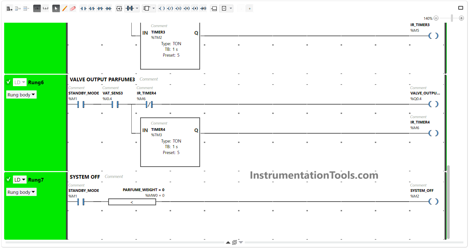
RUNG 7 (SYSTEM OFF)
The memory bit SYSTEM_OFF (M2) will change to a HIGH state when the NO contact of memory bit STANDBY_MODE (M1) in the HIGH state and the value in memory word PARFUME_WEIGHT (MW0) is equal to zero “0”.
Read Next:
- Sequential Batch Mixing PLC Programming
- Basic PLC Exercise on Heater and Cooler
- PLC Program for Sequential Motor Control
- Schneider PLC Logic for Star-Delta System
- Schneider PLC Manual Sequential Machine