This article is about the function of the masking in the PLC. Here, I will use Siemens TIA PORTAL.
Masking helps us to cover something or mask which you don’t want to see. In the PLC terms Masking means to filter the data which you don’t want to use while execution of the PLC programming.
You may have noticed when you make a purchase, At the time of payment when you enter your ATM card number, it won’t allow you to use any alphabet that what you can call is masking.
Masking in PLC
Let’s understand the function of masking with an example. Do follow the below example and also play around with the different values to understand it.
For example, let say I have a temperature transmitter. As this is an analog signal data type, so we need a word or doubleword data type.
I want that if PLC receives a signal from a temperature transmitter, I need some data to masked off. The bit which I want to mask off is “00FF” which in binary represented as “0000 0000 1111 1111”.
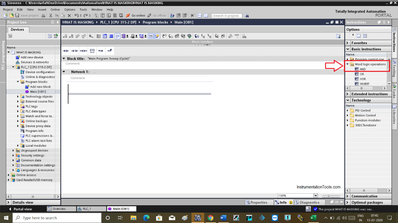
Now we will implement the above example. Open TIA PORTAL.
In the logic operation, add AND instruction.
I already have covered an article on logic instruction. Please find it from somewhere down and read it.
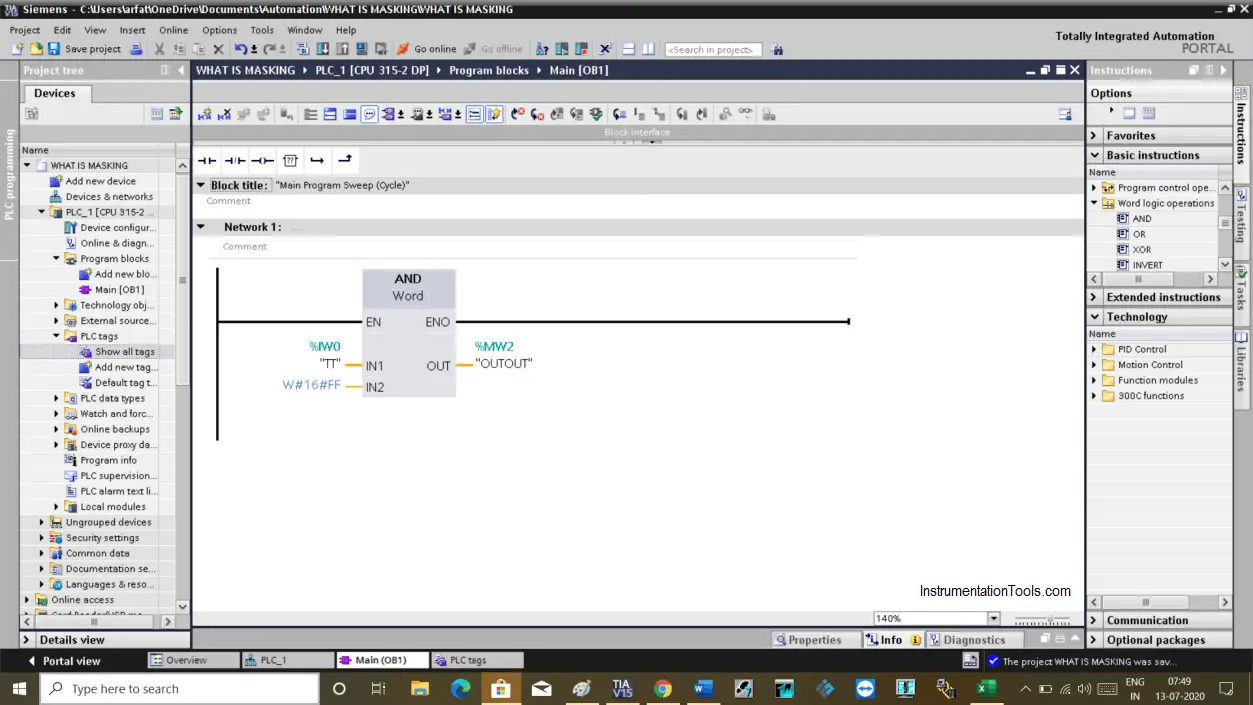
In this below window I added AND instruction to mask off some data coming from the temperature transmitter.
In “IN1”, IW0 is an input signal which is coming from the temperature transmitter. In “IN2”, I have used “00FF” which is a value that I want to mask off. The output of ANDing will be written to a memory word MW2.
You can use other logic instructions too and also you can play with a value to know the function of the masking.
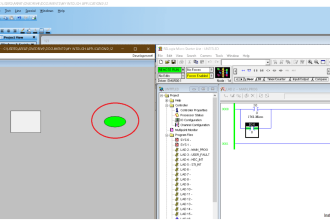
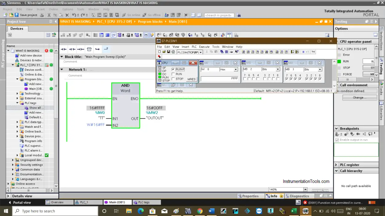
If I run the logic, you can see the result in the below window.
In IN1, I have used “FFFF” which in binary represented by 1111 1111 1111 1111.
In IN2, I have used “00FF” which in binary represented by 0000 0000 1111 1111.
As I have used ANDing operation, we know that when both inputs are “1” then the only output will be energized.
The ANDing result in the output you can get is “0000 0000 1111 1111”. Which you can see in the simulation window.
This is how masking can be done. If you still have any question or any doubt then put your question in the comment section.
Author: Suhel Patel
If you liked this article, then please subscribe to our YouTube Channel for PLC and SCADA video tutorials.
You can also follow us on Facebook and Twitter to receive daily updates.
Read Next:
- Midline Instruction in PLC
- Create a Project in LabVIEW
- Turbine Temperature Alarms
- Communication Processor Module
- Delete the Siemens CPU Memory