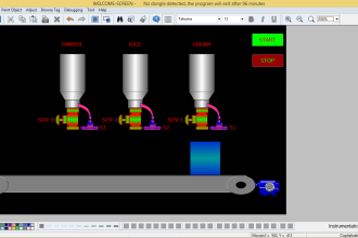
This article discusses the implementation of a Machine Sequential System that is operated manually using Schneider PLC.
In this article, we will discuss an example PLC Program that controls 4 different machines with one push button using Ecostruxure Machine Expert-Basic software.
Manual Sequential Machine
This PLC system uses 4 buttons, the START_SYSTEM (I0.0) button is used to Turn On the system (standby state), the STOP_SYSTEM (I0.1) button is used to Turn Off the system, the RUN_SYSTEM (I0.2) button is used to RUN the system, the RESET_SEQUENCE (I0.3) button is used to Reset the counter sequence data.
When START_SYSTEM (I0.0) button is Pressed, the memory bit SYSTEM_ON (M0) becomes a HIGH state and the system will be in a Standby state. The system will be OFF if the STOP_SYSTEM (I0.1) button is Pressed.
The PLC program has 4 sequences stored in memory word SEQUENCE (MW0). Sequence data can be Reset to zero “0” using the RESET_SEQUENCE (I0.3) button.
Sequence 1, when the RUN_SYSTEM (I0.2) button is pressed, the value in memory word SEQUENCE (MW0) becomes “1” and Output MACHINE1 (Q0.0) will be ON for 5 seconds.
Sequence 2, when the RUN_SYSTEM (I0.2) button is Pressed again, the value in memory word SEQUENCE (MW0) increases (+1) to “2” and Output MACHINE2 (Q0.1) will be ON for 6 seconds.
Sequence 3, when the RUN_SYSTEM (I0.2) button is Pressed again, the value in memory word SEQUENCE (MW0) increases (+1) to “3” and Output MACHINE3 (Q0.2) will be ON for 7 seconds.
Sequence 4, when the RUN_SYSTEM (I0.2) button is Pressed again, the value in memory word SEQUENCE (MW0) increases (+1) to “4” and Output MACHINE4 (Q0.3) will be ON for 8 seconds.
After the MACHINE4 (Q0.3) output changes to the OFF state, the data in memory word SEQUENCE(MW0) is reset to zero “0”.
Inputs and Outputs Details
| Comment | Input (I) | Output (Q) | Memory Bits | Memory Word | Timers |
| START_SYSTEM | I0.0 | ||||
| STOP_SYSTEM | I0.1 | ||||
| RUN_SYSTEM | I0.2 | ||||
| RESET_SEQUENCE | I0.3 | ||||
| MACHINE1 | Q0.0 | ||||
| MACHINE2 | Q0.1 | ||||
| MACHINE3 | Q0.2 | ||||
| MACHINE4 | Q0.3 | ||||
| TIMER1 | TM0 | ||||
| TIMER2 | TM1 | ||||
| TIMER3 | TM2 | ||||
| TIMER4 | TM3 | ||||
| SYSTEM_ON | M0 | ||||
| IR_TIMER1 | M1 | ||||
| IR_TIMER2 | M2 | ||||
| IR_TIMER3 | M3 | ||||
| IR_TIMER4 | M4 | ||||
| SEQUENCE | MW0 |
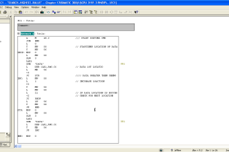
Programming Schneider PLC
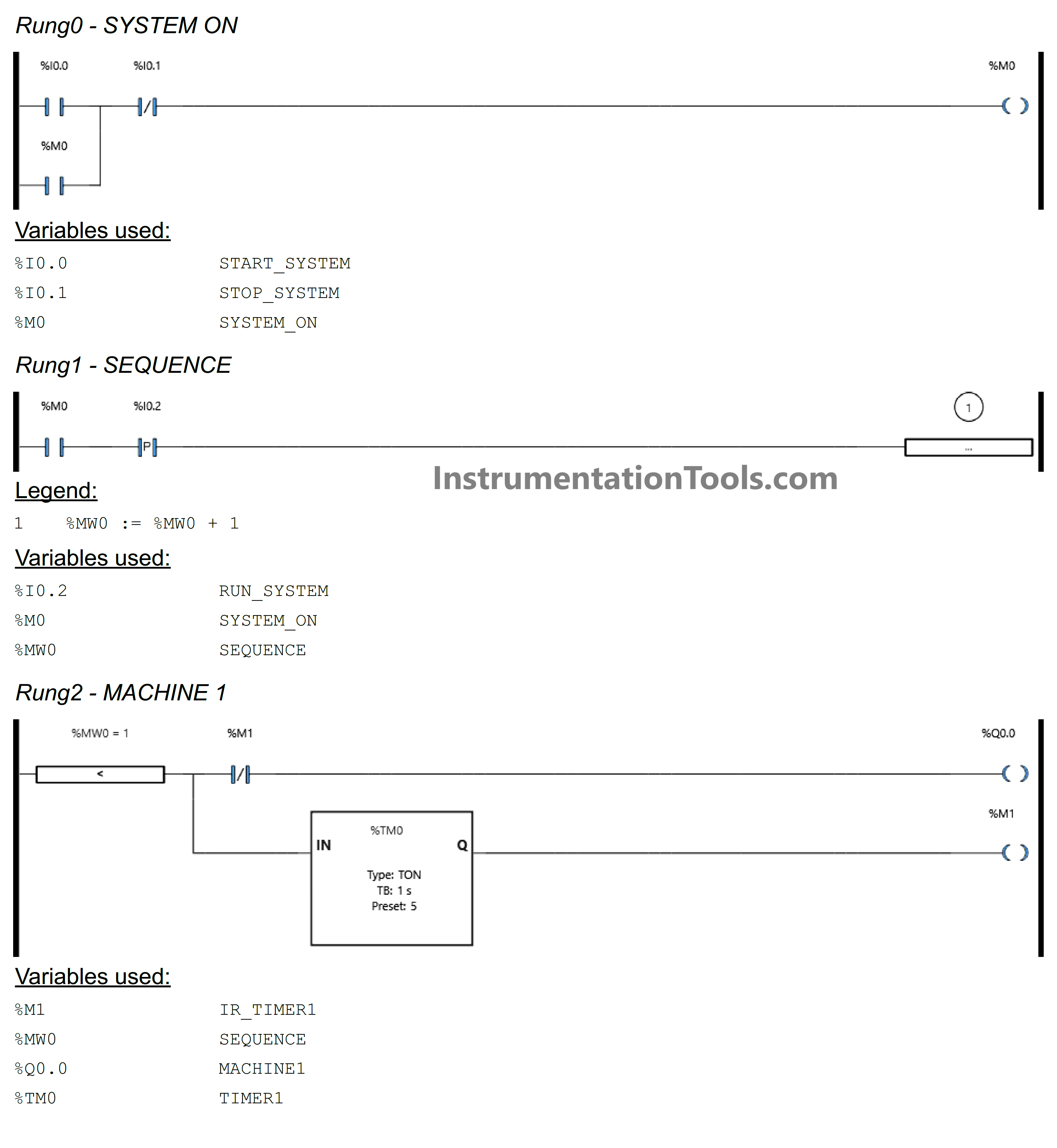
RUNG 0 (SYSTEM ON)
When the START_SYSTEM (I0.0) button is Pressed, the memory bit SYSTEM_ON (M0) changes to HIGH state. The memory bit SYSTEM_ON (M0) remains HIGH even though the START_SYSTEM (I0.0) button has been Released because it uses Latching.
The SYSTEM_ON (M0) memory bit will be in LOW state if the STOP_SYSTEM (I0.1) button is Pressed.
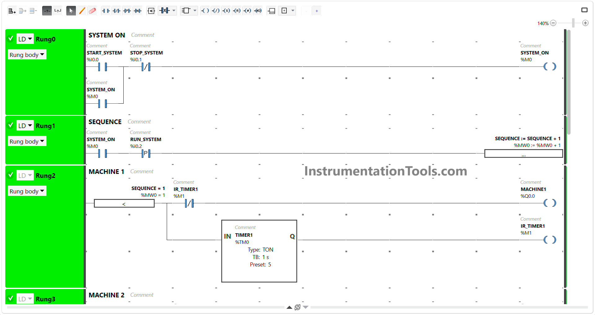
RUNG 1 (SEQUENCE)
In this Rung, when the NO contact of memory bit SYSTEM_ON (M0) in HIGH state and the RUN_SYSTEM (I0.2) button is pressed, the data in memory word SEQUENCE (MW0) will increase (+1).
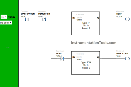
RUNG 2 (MACHINE 1)
In this Rung, Output MACHINE1 (Q0.0) will be ON and the Timer instruction TIMER1 (TM0) starts counting when the value in memory word SEQUENCE (MW0) is equal to “1”. Timer TIMER1 (TM0) will count up to 5 seconds.
When Timer TIMER1 (TM0) finishes counting, then the memory bit IR_TIMER1 (M1) will be in a HIGH state and Output MACHINE1 (Q0.0) will be OFF because of the Interlock.
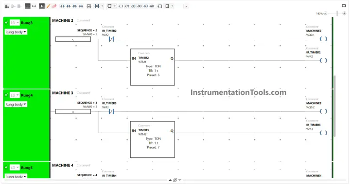
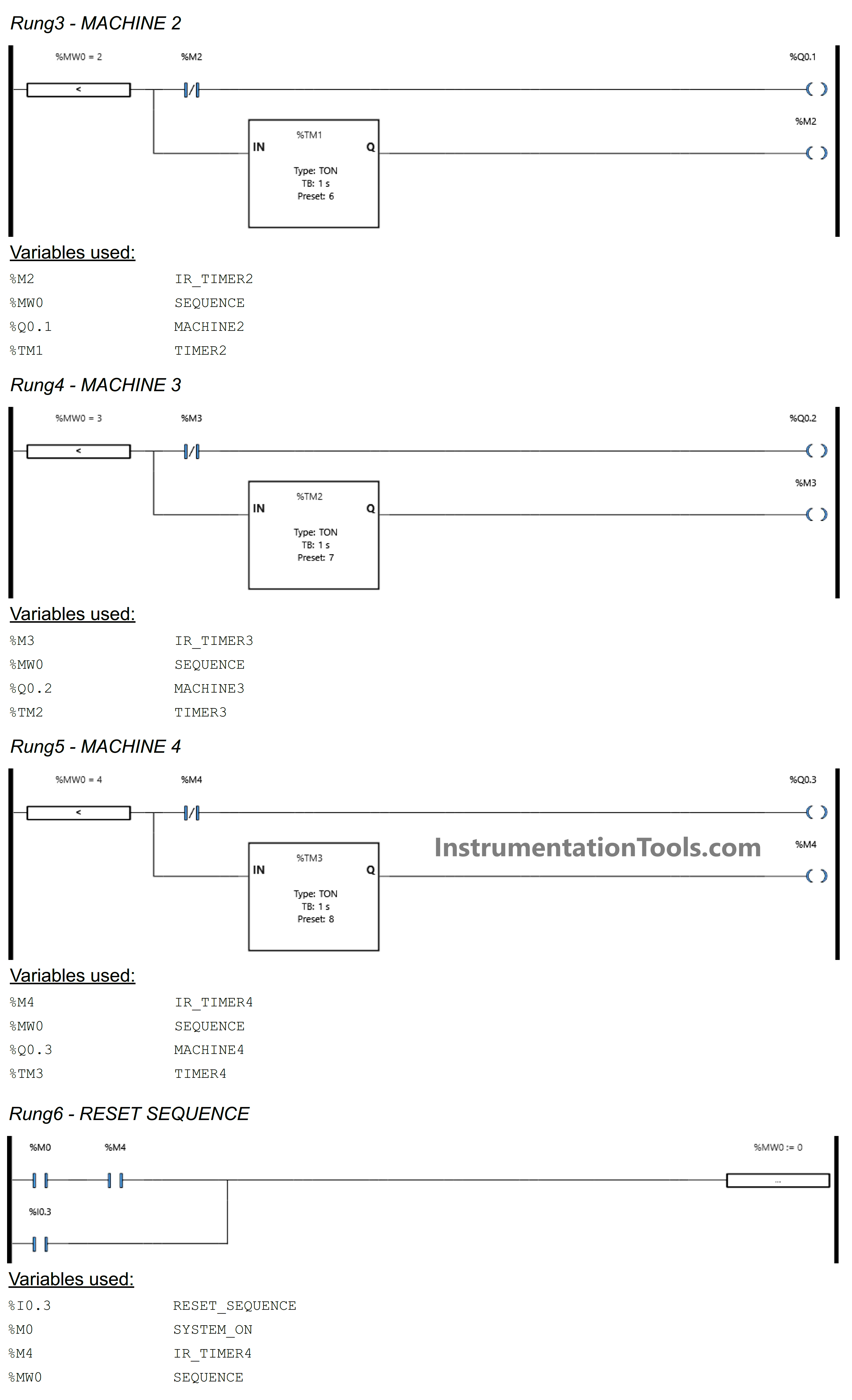
RUNG 3 (MACHINE 2)
In this Rung, Output MACHINE2 (Q0.1) will be ON and the Timer instruction TIMER2 (TM1) starts counting when the value in memory word SEQUENCE (MW0) is equal to “2”. The TIMER2 (TM1) timer will count up to 6 seconds.
When Timer TIMER2 (TM1) finishes counting, the memory bit IR_TIMER2 (M2) will be in a HIGH state and Output MACHINE2 (Q0.1) will become OFF due to the Interlock.
RUNG 4 (MACHINE 3)
In this Rung, Output MACHINE3 (Q0.2) will be ON and the Timer instruction TIMER3 (TM2) starts counting when the value in memory word SEQUENCE (MW0) is equal to “3”. The TIMER3 (TM2) timer will count up to 7 seconds.
When Timer TIMER3 (TM2) finishes counting, the memory bit IR_TIMER3 (M3) will be in a HIGH state and Output MACHINE3 (Q0.2) will become OFF due to the Interlock.
RUNG 5 (MACHINE 4)
In this Rung, Output MACHINE4 (Q0.3) will be ON and the Timer instruction TIMER4 (TM3) starts counting when the value in memory word SEQUENCE (MW0) is equal to “4”. The TIMER4 (TM3) timer will count up to 8 seconds.
When Timer TIMER4 (TM3) finishes counting, the memory bit IR_TIMER4 (M4) will be in a HIGH state and Output MACHINE4 (Q0.3) will become OFF due to the Interlock.
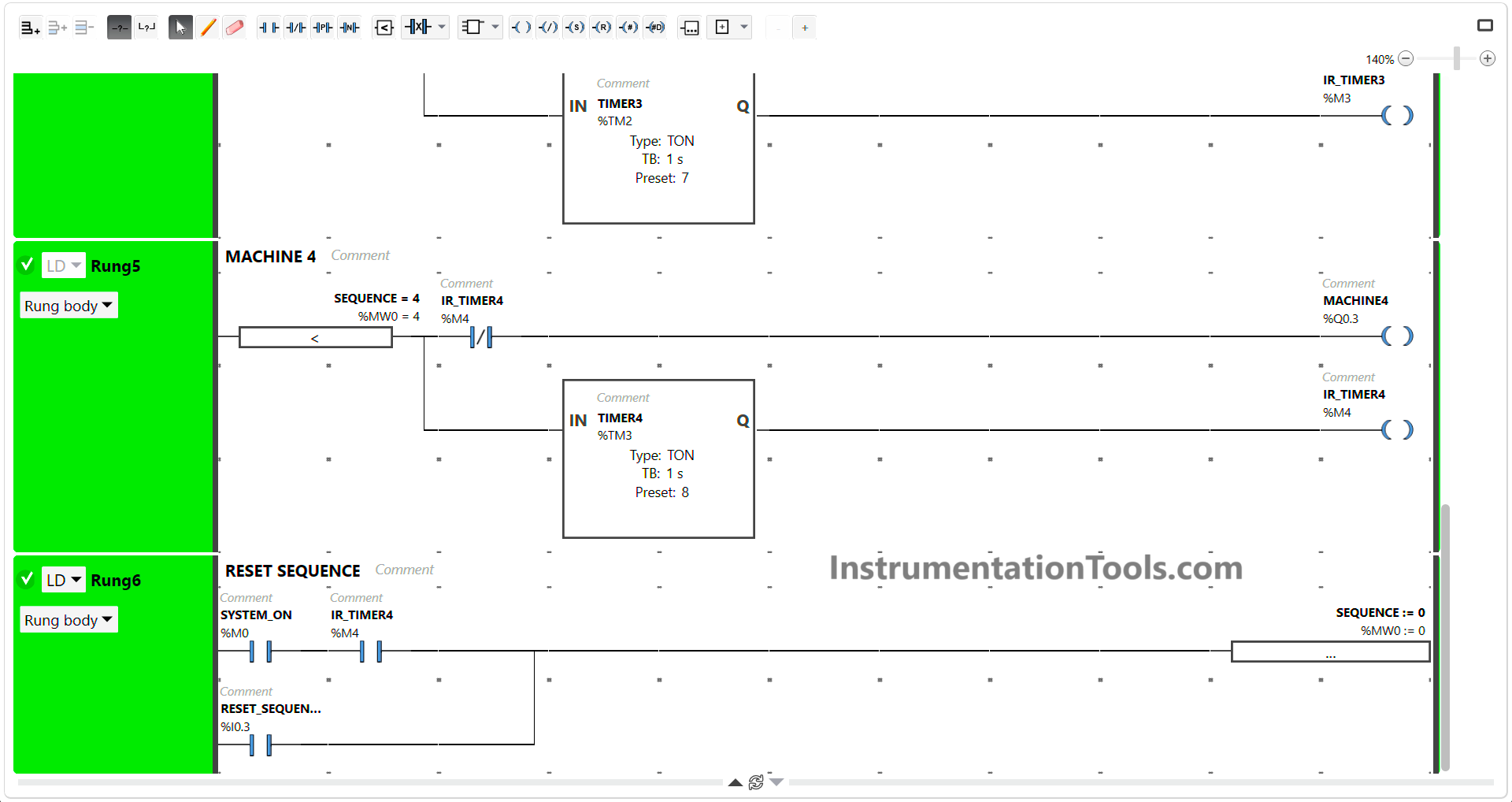
RUNG 6 (RESET SEQUENCE)
In this Rung, when the NO contacts of memory bits SYSTEM_ON (M0) and IR_TIMER4 (M4) are in the HIGH state, the memory word SEQUENCE (MW0) changes to the value “0”.
Or, when the RESET_SEQUENCE (I0.3) button is Pressed, the memory word SEQUENCE (MW0) becomes “0”.
Operation Block will move the value “0” to the memory word SEQUENCE (MW0).
Read Next:
- Sequential Batch Mixing PLC Programming
- Pump and Mixer Operations PLC Example
- PLC Program for Sequential Motor Control
- 3 to 8 Line Decoder PLC Ladder Diagram
- Schneider PLC Logic for Star-Delta System


It’s a good start. You used a master calling action based on its value. You manipulate the value based on what the machine needs to do. It’s the right way of thinking as it enable doing multiple tasks in parallel.
What I see that can be improved is:
– First cycle scan to reset the memory to 0
– Improve the fltering of the input. Just a pulse will not protect from an electrical flickering.
– Add protection to force step completion before authorizing the next step. In your scenario an operator could jump to next step before the preceding step is completed.
– Add initial conditions to initiate the sequencing.
– Add a way to pause and restart a step
– Add basic machine safety, in this case an E-Stop. It should be hardwired but it should also come back to the PLC.