Calculate the voltage drops in this loop-powered 4-20 mA transmitter circuit for the current conditions 4mA, 8mA, 12mA, 20mA.
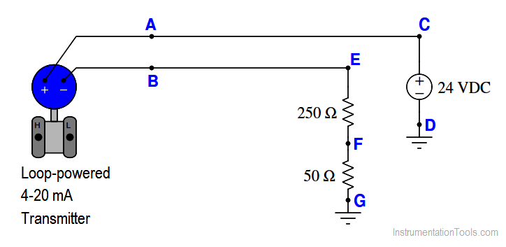
Calculate the voltage drop at different points in the above circuit, like VCD, VEF, VFG, VAB at different loop currents (4mA, 8mA, 12mA, and 20mA)
In order for a loop-powered transmitter such as this to function adequately, there must be a minimum DC voltage between its terminals (VAB) at all times.
A typical value for this voltage is 12 volts (be aware that this minimum voltage level varies considerably between different manufacturers and models!). Identify what loop condition(s) may jeopardize this minimum supply voltage value, and how you as a technician would ensure the transmitter always received enough voltage to function.
The Rosemount 3144 temperature transmitter, for example, requires a minimum of 12 volts at its terminals to function in the analog mode, and 18.1 volts in order to properly function while communicating using the HART digital-over-analog protocol.
Note how the operation of such a 3144 transmitter in a loop with a 24 volt power supply and 300 ohms worth of resistance would be jeopardized near the upper end of the signal range.
Share Your Answers for the remaining questions.
Credits: Tony R. Kuphaldt
The conveyor sorting machine is widely used in the packing industries using the PLC program…
Learn the example of flip-flop PLC program for lamps application using the ladder logic to…
In this article, you will learn the STAR DELTA programming using PLC controller to start…
Lube oil consoles of rotary equipment packages in industrial process plants are usually equipped with…
Rotating equipment packages such as pumps, compressors, turbines need the lube oil consoles for their…
This article explains how to blink lights in ladder logic with a detailed explanation video…


View Comments
1- increase .
2- I am not sure and i hope to known the reason for that , I think we used multiple resistances to compare the value of volts for each resistance the insurance that is no deviation or drop of voltage .
3-we can used multimeter to read values for each segment between nodes and used Kirchhoff voltage law then compare the results with state of level transmitter.
What about the internal resistance of the transmitter? why it is not taken into account ?