Inst ToolsInst ToolsInst Tools
  • Ask
  • Courses
  • Videos
  • Q & A
    • Interview
      • Instrumentation
      • Electronics
      • Electrical
      • Practical Questions
    • MCQ
      • Instrumentation MCQ
      • Electrical MCQ
      • Electronics MCQ
      • Control Systems MCQ
      • Analog Electronics MCQ
      • Digital Electronics MCQ
      • Power Electronics MCQ
      • Microprocessor MCQ
      • Multiple Choice Questions
  • EE
    • Electronics
      • Electronics Q & A
      • Electronic Basics
      • Electronic Devices & Circuits
      • Electronics Animation
      • Digital Electronics
    • Electrical
      • Electrical Basics
      • Electrical Q & A
      • Power Electronics
      • Electrical Machines
      • Electrical Animation
      • Power Systems
      • Switchgear & Protection
      • Transmission & Distribution
  • Measure
    • Control Valves
    • Calibration
    • Temperature
    • Pressure
    • Flow
    • Level
    • Analyzers
    • Switches
    • Vibration
    • Solenoid Valve
  • Control
    • PLC Tutorials
    • Control Systems
    • Safety Instrumented System (SIS)
    • Communication
    • Fire & Gas System
  • More
    • Design
    • Tools
    • Animation
    • Basics
    • Formulas
    • Standards
    • TextBooks
    • Common
    • Software
    • Excel Tools
    • Erection & Commissioning
    • Process Fundamentals
    • Videos
    • Books
Search
All rights reserved. Reproduction in whole or in part without written permission is prohibited.
Reading: Lobed Impeller Flow Meters Working Principle
Share
Notification Show More
Font ResizerAa
Inst ToolsInst Tools
Font ResizerAa
  • Courses
  • PLC Tutorials
  • Control Systems
Search
  • Ask
  • Courses
  • Videos
  • Q & A
    • Interview
    • MCQ
  • EE
    • Electronics
    • Electrical
  • Measure
    • Control Valves
    • Calibration
    • Temperature
    • Pressure
    • Flow
    • Level
    • Analyzers
    • Switches
    • Vibration
    • Solenoid Valve
  • Control
    • PLC Tutorials
    • Control Systems
    • Safety Instrumented System (SIS)
    • Communication
    • Fire & Gas System
  • More
    • Design
    • Tools
    • Animation
    • Basics
    • Formulas
    • Standards
    • TextBooks
    • Common
    • Software
    • Excel Tools
    • Erection & Commissioning
    • Process Fundamentals
    • Videos
    • Books
Follow US
All rights reserved. Reproduction in whole or in part without written permission is prohibited.
Inst Tools > Blog > Flow Measurement > Lobed Impeller Flow Meters Working Principle

Lobed Impeller Flow Meters Working Principle

Lobed impeller flow meters consist of two impellers rotating in opposite directions due to the forces exerted by the gas flow being measured.

Last updated: October 31, 2023 3:32 pm
Editorial Staff
Flow Measurement
No Comments
Share
3 Min Read
SHARE

Two rotating impellers, designed with a figure eight cross-section, rotate in opposite directions due to the forces exerted by the gas flow being measured.

Contents
Lobed Impeller Flow MetersAdvantages of Lobed Impeller Flow MetersLimitations of Lobed Impeller Flow Meters

The shape of the impellers prevents contact while the gap between them remains constant.

Lobed Impeller Flow Meters

Lobed Impeller Flow Meters Working Principle

A gear drive external to the measuring chamber synchronizes the impellers. During each rotation, four crescent-shaped volumes are moved through the measuring chamber. The number of rotations is proportional to the flow. The rotation is coupled using an adjustable fine-tooth gear train to the totalizer.

An unmeasured flow, which is a function of the pressure drop, flows through the gaps. The negative error is compensated by an adjustment. The viscosity of flow increases at high pressures and reduces the losses in the gaps which compensates for the higher losses which would otherwise exist due to the higher pressure difference.

The pulsations in the flow discharge can cause the pipe system connected to the meter to vibrate. If resonance should occur, loud noises and sudden pressure drops can result. This condition should not be allowed to occur; if necessary noise or pulsation dampers should be utilized.
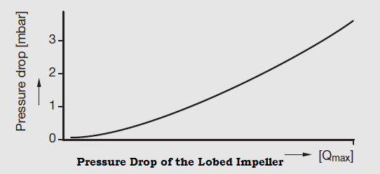
Lobed Impeller Flow Meters Graph

The pressure drop results from the mechanical and dynamic resistances in the meter. The dynamic portion increases appreciably with increasing load.

Lobed impeller meters are very susceptible to contamination. Since contamination affects the pressure drop it must be monitored and the meter cleaned when required.

Advantages of Lobed Impeller Flow Meters

  • Excellent measuring accuracy for gas measurements
  • No inlet and outlet sections required
  • No external power supply

Limitations of Lobed Impeller Flow Meters

  • Volume totalizer
  • For gases only
  • Moving parts, wear
  • Flow blockage at zero flow through solid impurities
  • Sluggish toward quick changes
  • Also affected by quick changes at high differential pressure, the danger of over speeding
  • Monitoring

If you liked this article, then please subscribe to our YouTube Channel for Instrumentation, Electrical, PLC, and SCADA video tutorials.

You can also follow us on Facebook and Twitter to receive daily updates.

Read Next:

  • Piston Flow Meters Working
  • Multi-phase Flow Meter
  • Advantages of Flow Meter
  • Different Flow Meters Types
  • What is an Orifice Flow Meter?
Don't Miss Our Updates
Be the first to get exclusive content straight to your email.
We promise not to spam you. You can unsubscribe at any time.
Invalid email address
You've successfully subscribed !

Recommended Articles

Working Principle of Flow Switch with Animation
What is a Turbine Flow Meter?
Oval Gear Flow Meters – Principle, Advantages, Animation
Volumetric Flow Calculations
What is Integral Flow Orifice Assembly?
Swirl Flow Meters Working Principle
Share This Article
Facebook Whatsapp Whatsapp LinkedIn Copy Link
Share
Leave a Comment

Leave a Reply Cancel reply

Your email address will not be published. Required fields are marked *

Stay Connected

128.3kFollowersLike
69.1kFollowersFollow
208kSubscribersSubscribe
38kFollowersFollow

Categories

Recent Comments

  • William Snyder on Top Non-PLC Certification Courses for Automation Professionals
  • Kamli on Top Free PLC Software
  • Guifty Shimica on Top Non-PLC Certification Courses for Automation Professionals
  • Guifty Shimica on Top Non-PLC Certification Courses for Automation Professionals

Related Articles

flow Nozzle

Flow Nozzle Principle, Advantages, Disadvantages, Applications

V Cone Flow Meter Working Principle

V Cone Flow Meter – Principle, Advantages, Disadvantages

Flow Switch Symbol

Principle of Flow Switch

Pressure and Temperature Compensation for Flow Transmitter

Why Pressure & Temperature Compensation required for Orifice Flow Meters ?

Vortex Flow GIF

Working Principle of Vortex Flow Meter

difference between invasive and non-invasive and intrusive and non-intrusive

Difference between Invasive, Non-invasive, Intrusive & Non-intrusive

Comparison of Flowmeters

Difference between Different Types of Flow Meters

Flow Measurement Questions and Answers

80+ Flow Measurement Interview Questions and Answers

More Articles

ISA and SAMA diagrams

What is SAMA Diagram?

Power Electronics Objective Questions

AC Voltage Controllers Multiple Choice Questions

Siemens CP Module

Communication Processor Module in Siemens PLC

RTD Calibration

RTD Calibration

Heat Tracing Problems

Heat Tracing Problems

Wet Leg Level Transmitter

Basics of DP Level Measurement

Hydrostatic pressure Measurement

Basics of Hydrostatic Level Measurement

PLC 1 Push Button to Turn ON or OFF 1 Output

PLC 1 Push Button to Turn ON or OFF 1 Output

Follow US
All rights reserved. Reproduction in whole or in part without written permission is prohibited.
Welcome Back!

Sign in to your account

Username or Email Address
Password

Lost your password?