Inst ToolsInst ToolsInst Tools
  • Courses
  • Automation
    • PLC
    • Control System
    • Safety System
    • Communication
    • Fire & Gas System
  • Instrumentation
    • Design
    • Pressure
    • Temperature
    • Flow
    • Level
    • Vibration
    • Analyzer
    • Control Valve
    • Switch
    • Calibration
    • Erection & Commissioning
  • Interview
    • Instrumentation
    • Electrical
    • Electronics
    • Practical
  • Q&A
    • Instrumentation
    • Control System
    • Electrical
    • Electronics
    • Analog Electronics
    • Digital Electronics
    • Power Electronics
    • Microprocessor
Search
  • Books
  • Software
  • Projects
  • Process
  • Tools
  • Basics
  • Formula
  • Power Plant
  • Root Cause Analysis
  • Electrical Basics
  • Animation
  • Standards
  • 4-20 mA Course
  • Siemens PLC Course
Reading: Limit, Selector, and Override controls
Share
Notification Show More
Font ResizerAa
Inst ToolsInst Tools
Font ResizerAa
  • Courses
  • Design
  • PLC
  • Interview
  • Control System
Search
  • Courses
  • Automation
    • PLC
    • Control System
    • Safety System
    • Communication
    • Fire & Gas System
  • Instrumentation
    • Design
    • Pressure
    • Temperature
    • Flow
    • Level
    • Vibration
    • Analyzer
    • Control Valve
    • Switch
    • Calibration
    • Erection & Commissioning
  • Interview
    • Instrumentation
    • Electrical
    • Electronics
    • Practical
  • Q&A
    • Instrumentation
    • Control System
    • Electrical
    • Electronics
    • Analog Electronics
    • Digital Electronics
    • Power Electronics
    • Microprocessor
Follow US
All rights reserved. Reproduction in whole or in part without written permission is prohibited.
Inst Tools > Blog > Control Systems > Limit, Selector, and Override controls

Limit, Selector, and Override controls

Last updated: August 22, 2019 4:30 pm
Editorial Staff
Control Systems
1 Comment
Share
4 Min Read
SHARE

Another category of control strategies involves the use of signal relays or function blocks with the ability to switch between different signal values, or re-direct signals to new pathways.

Such functions are useful when we need a control system to choose between multiple signals of differing value in order to make the best control decisions.

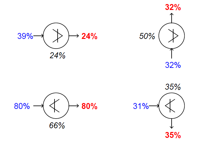
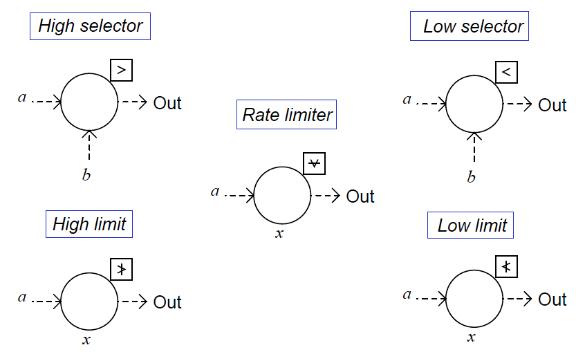
The “building blocks” of such control strategies are special relays (or function blocks in a digital control system) shown here:

Limit, Selector, and Override controls

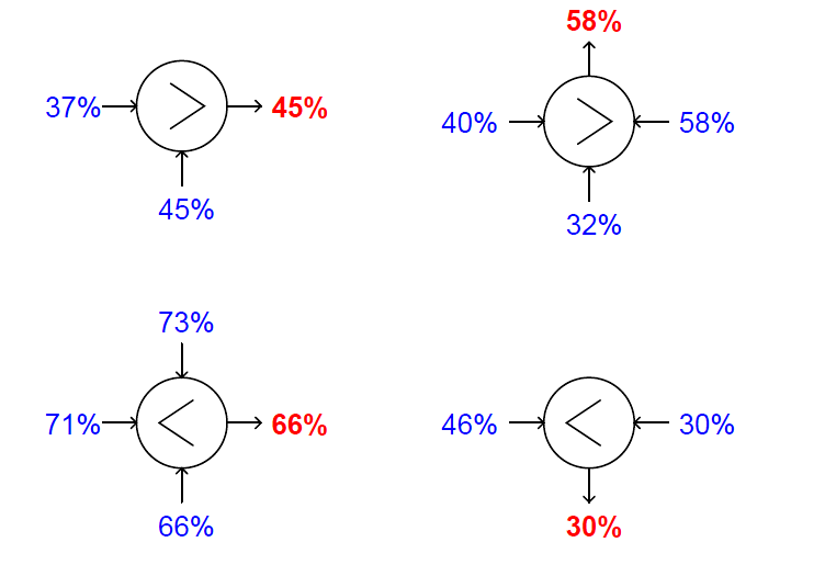
High-select functions output whichever input signal has the greatest value. Low-select functions do just the opposite: output whichever input signal has the least value.

“Greater-than” and “Less than” symbols mark these two selector functions, respectively, and each type may be equipped to receive more than two input signals.

Sometimes you will see these relays represented in P&IDs simply by an inequality sign in the middle of the large bubble, rather than off to the side in a square.

You should bear in mind that the location of the input lines has no relationship at all to the direction of the inequality symbol – e.g., it is not as though a high-select relay looks for the input on the left side to be greater than the input on the right.

Note the examples shown below, complete with sample signal values:

DCS Switch Functions

High-limit and low-limit functions are similar to high- and low-select functions, but they only receive one input each, and the limit value is a parameter programmed into the function rather than received from another source.

The purpose of these functions is to place a set limit on how high or how low a signal value is allowed to go before being passed on to another portion of the control system.

If the signal value lies within the limit imposed by the function, the input signal value is simply passed on to the output with no modification.

Like the select functions, limit functions may appear in diagrams with nothing more than the limit symbol inside the bubble, rather than being drawn in a box off to the side:

High-limit and low-limit switch functions

Rate limit functions place a maximum rate-of-change limit on the input signal, such that the output signal will follow the input signal precisely until and unless the input signal’s rate-of-change over time ( dx/dt ) exceeds the pre-configured limit value.

In that case, the relay still produces a ramping output value, but the rate of that ramp remains fixed at the limit dx/dt value no matter how fast the input keeps changing.

After the output value “catches up” with the input value, the function once again will output a value precisely matching the input unless the input begins to rise or fall at too fast a rate again.

Also Read : Limit Controls : High Limit & Low Limit Functions
Don't Miss Our Updates
Be the first to get exclusive content straight to your email.
We promise not to spam you. You can unsubscribe at any time.
Invalid email address
You've successfully subscribed !

Continue Reading

Supervisory Control
Liquid Level Switch Control Pump and Lamp
Yokogawa DCS Tutorials – Configuration of Analog Input (Transmitter)
Why Use a Current Loop?
Difference between Feedback, Feedforward, and Cascade Control?
Control Loops Objective Questions and Answers
Share This Article
Facebook Whatsapp Whatsapp LinkedIn Copy Link
Share
1 Comment
  • Usama Iskander says:
    March 23, 2018 at 3:05 am

    Dear Sir
    i need a Fisher Valve CASCADE CONTROL

    Reply

Leave a Reply Cancel reply

Your email address will not be published. Required fields are marked *

Stay Connected

128.3kFollowersLike
69.1kFollowersFollow
208kSubscribersSubscribe
38kFollowersFollow

Categories

Explore More

Power Supply Sizing for Industrial Automation Systems
Five Levels in Industrial Automation
How to Design a Motor Faceplate in Graphics? – SCADA Tutorials
Power Factor Controller (PFC) – Commissioning
Relay Operation, Types, Symbols & Characteristics
Modbus Function Codes and Addresses
Determining the Design Purpose of Override Controls
Purpose of Gateways, Bridges & Routers in Networking

Keep Learning

Process Control Fundamentals

Process Control Fundamentals

ESD System Insights

ESD System Insights: Signals for Emergency Valve Shutdown Explained

Distributed Control System & Motor Control Center Interface Philosophy

Distributed Control System & Motor Control Center Interface Philosophy

Override Control Functions

What is Override Control? – Need & Applications

DCS Alarm Summary Dashboard using Microsoft Power BI

DCS Alarm Summary Dashboard using Microsoft Power BI

Electrical Drives Animation

Electrical Drives – Modes, Types, Speed Control Applications

Cable Glands

Using of MCT instead of Cable Glands on the Cabinets

Digital Output Card With Relay and Wet Contact

Wiring Diagrams of PLC and DCS Systems – DI, DO, AI, AO

Learn More

Electrical Engineers Basics

Basic Electrical Engineering Questions & Answers

Pneumatic Training Course - Download PDF

Pneumatic Training Course – Download PDF

Electric Drives and Traction Objective Questions and Answers

Electric Drives and Traction Interview Questions

Gas Detectors Calibration

Calibration of Gas Detectors

Temperature Gauges and Elements Specifications

Temperature Gauges and Elements : Detailed Specifications

PLC Programming Example on Timers Function Block

PLC Programming Example on Timers Function Block

WirelessHART Principle

Wireless HART Communication Protocol Overview

Retentive ON delay timer using PLC Logic

Retentive ON Delay Timer using PLC

Follow US
All rights reserved. Reproduction in whole or in part without written permission is prohibited.
Welcome Back!

Sign in to your account

Username or Email Address
Password

Lost your password?