After getting your prototype sketch approved by the instructor, you are cleared to begin building your system.
Transmitters attach to 2-inch pipes using special brackets and U-bolts. These brackets and U-bolts are located along with the transmitters in the instrument storage area.
Feel free to use 1/4 inch plastic tubing for all the pneumatic signal connections, and be sure not to exceed the rated supply pressure (as documented in the transmitter’s manual).
Finally, your level-measurement system needs to have a loop number, so all instruments may be properly labeled. This loop number needs to be unique, so that another team does nottheir instruments and tubes the same as yours.
One way to make your loop number unique is to use the equivalent resistor color code value for your team’s color in the loop number. For example, if you are on the “Red” team, your loop number could be “2”.
It is recommended that you use a different electronic indicator or indicating controller as the display unit on this lab exercise, to give yourself wider exposure to the controller/indicator options in our lab facility.
For example, if in the previous lab exercise your team used a panel-mount electronic indicating controller, consider using a PLC or a DCS as the electronic indicator in this lab exercise.
Neglecting to consult the manufacturer’s documentation for field instruments (e.g. how to connect pneumatic signal lines, how to calibrate them).
Mounting the field instrument(s) in awkward positions, making it difficult to reach tube connectors or to remove covers when installed.
Mounting the transmitter above the LRV point, rather than below (to avoid loss of impulse line liquid fill when the vessel’s level is drained to the LRV point).
Improper pipe/tube fitting installation (e.g. trying to thread tube fittings into pipe fittings and vice-versa).
Applying Teflon tape to tube fitting threads; failing to apply Teflon tape to pipe fitting threads.
Over-tightening tube fittings (remember, no more than 1-1/4 turns when installing a new ferrule set, and no more than “snug” when re-making the connection!).
Students working on portions of the system in isolation, not sharing with their teammates what they did and how. It is important that the whole team learns all aspects of their system!
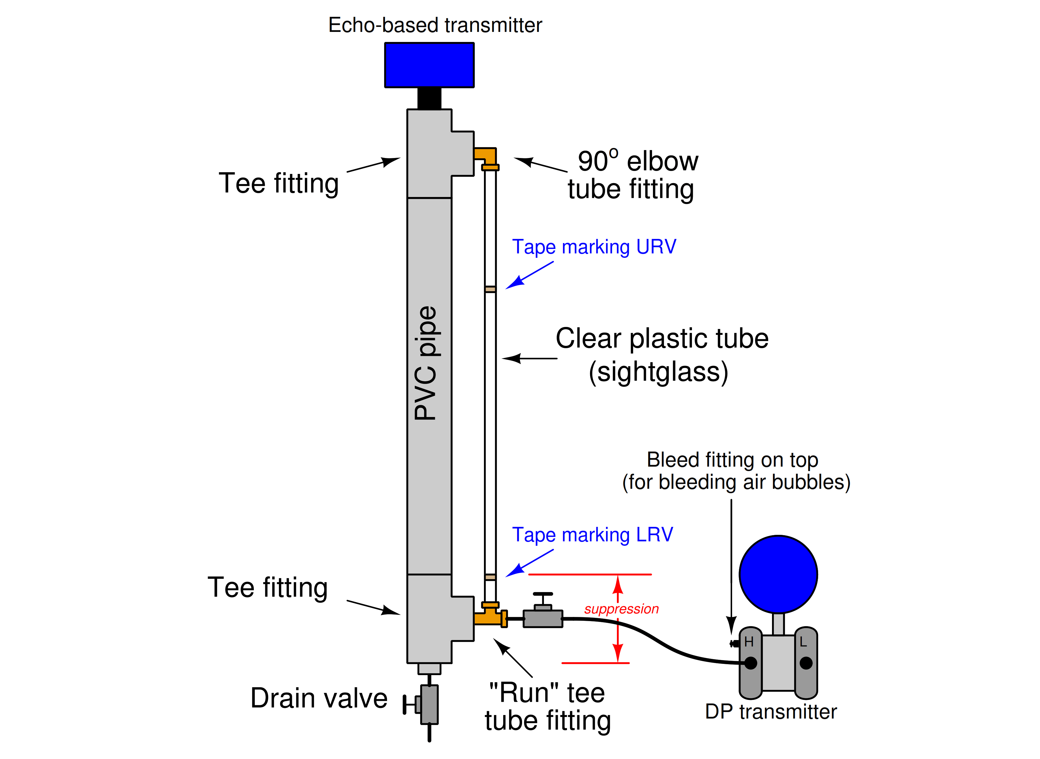
It is relatively easy to construct a “process vessel” for measuring water level in, by using inexpensive PVC plastic piping and fittings:

Water is poured in the top, through the open tee fitting, and is drained through a valve at the bottom (preferably a 1/4 turn ball valve).
Even with an instrument valve manifold on the ∆P transmitter, a shutoff valve is advisable between the process vessel connection and the transmitter to facilitate the removal of the transmitter and manifold without having to drain the vessel.
Note how the DP transmitter is mounted lower than the LRV mark on the sight-glass: this is intentional, as it maintains a liquid fill throughout the impulse line even when the vessel is at its lowest liquid level.
If the transmitter is mounted above this point, the possibility exists for that liquid fill to dribble out of the impulse line if ever the vessel’s level goes too low, and this loss of liquid fill will cause calibration errors!
Building a functioning system should take no more than one full lab session (3 hours) if all components are readily available and the team is working efficiently!
Read Next:
Credits: Tony R. Kuphaldt
Learn the example of flip-flop PLC program for lamps application using the ladder logic to…
In this article, you will learn the STAR DELTA programming using PLC controller to start…
Lube oil consoles of rotary equipment packages in industrial process plants are usually equipped with…
Rotating equipment packages such as pumps, compressors, turbines need the lube oil consoles for their…
This article explains how to blink lights in ladder logic with a detailed explanation video…
In this article, a simple example will teach you the conversion from Boolean algebra to…