Professional instrumentation audit checklist for oil & gas, chemical, and manufacturing industries. Ensure regulatory compliance, system reliability, and safety standards with this engineering audit.
Instrumentation Audit Checklist
Open the latest approved P&IDs (not the PDFs someone emailed last month). Walk the lines tag-by-tag—service, line number, and instrument tags must match what’s on the drawings and what’s in the field.
Cross-check the Instrument Index against P&IDs and loop/hook-up drawings. No orphan tags, no duplicates, and the status should be right (new/retain/remove).
Make sure the tag format is used the same way everywhere—DCS/PLC, SIS/ESD, historian, MCC lists, and vendor docs. If one system uses FT-101A and another uses FT101-A, fix it now.
Skim every datasheet: process conditions, ranges, wetted materials, pressure/temperature rating, ingress/Ex rating, approvals, and—importantly—revision history.
Pull the specs (instruments, valves, tubing, wiring, panels). Check they reference the current project/owner standards and any approved deviations are actually approved.
Open the hazardous area drawings. Confirm Ex zone/class, EPL, T-class, and max surface temperature line up with each device’s nameplate.
For intrinsically safe loops, confirm entity/FISCO parameters, barrier/isolator type, and the cable’s C/L values. Compare the loop calc to what’s actually installed.
Check environmental protection: IP/NEMA rating, UV/salt/corrosion protection, sunshades or rain hoods where needed, and the device’s ambient limits.
Verify wetted material compatibility with the fluid and temperature. If it’s sour service, confirm NACE MR0175/MR0103 call-outs and MTRs where applicable.
Confirm pressure/temperature ratings: MWP/MAWP/MOP should exceed design. Look for over-range protection (snubbers, seals, logic clamping) where the process is spiky.
Sanity-check calibration spans and accuracy vs control/safety needs. If a transmitter is working at 5% of span all year, rescale it.
Make sure calibration certificates are traceable (ISO/IEC 17025), in date, and the test equipment used was in date too.
Inspect hook-ups: impulse line sizes and slopes, condensate pots, capillaries, manifolds, root valves, and vent/drain points. No air traps where liquid should be, no dead legs where gas should be.
Check tapping points and orientations against standards; verify straight-run requirements for flow devices and that reducers/orifice taps match the datasheet.
Look at process connections: rating, gasket type, thread sealant use, torque. Confirm there’s a leak test record (hydro/pneumatic) where required.
For sampling/conditioning systems, check filters, pressure/temperature control, heat tracing, and lag volumes. Analyzer/transmitter must see the process, not the pipe lag.
Review control valve sizing reports: Cv, FL, xT, Reynolds correction; confirm noise (IEC 60534-8) and cavitation/flashing evaluations are present and sensible.
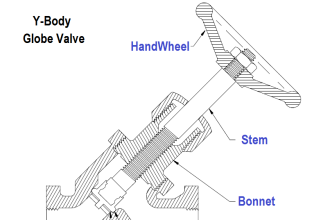
Validate valve selection: body/trim/seat, bonnet, packing, actuator sizing and fail action, positioner type, air set/boosters—does it match the service and the spec?
For on/off valves, confirm torque margins with safety factor at worst-case conditions, solenoid spec, FO/FC logic, partial-stroke testing (if used), and leak class (FCI 70-2/EN).
If PSVs/RVs interface to controls, check setpoints, proof seals, and any permissives or interlocks tied to them are correctly documented.
Walk the SIS lifecycle (IEC 61511): hazard analysis linkage → SRS → SIL verification (PFDavg) → proof-test intervals → bypass rules. The breadcrumbs should connect.
Compare Cause & Effect matrices to implemented logic. Trip setpoints, latching, resets, inhibits/bypasses, and alarm actions should behave exactly as written.
Check alarm management (ISA-18.2/IEC 62682): priority, deadbands, shelving rules, flood protection, and whether alarm KPIs are actually tracked.
Read the control narratives and click through the implemented logic. Modes (Auto/Man/Cascade), interlocks, permissives—does the operator faceplate reflect reality?
Review PLC/DCS code against your standard (IEC 61131-3): naming, comments, modular blocks, diagnostics, time stamping, and safe state on fault. Version control should tell a story.
Inspect HMI/SCADA graphics (ISA-101): color philosophy, units, scales, trends, faceplates, navigation, and P&ID references. Get rid of red-green Christmas trees.
Check historian/OPC mapping: tag names, EU, scan rates, compression, and clock sync (NTP/PTP). If time is off, everything is off.
Reconcile the I/O list: signal type/range, card slot/channel, JB/MB terminal, cable/core numbers—no gaps, no duplicates.
Open the marshalling cabinets: terminal numbering, segregation (AI/AO/DI/DO/IS/non-IS), ferrules, jumpers, wire markers, and tidy dress.
Review cable schedules: types and sizes, shielding and pair counts, tray routing and separation from power/VFDs, bend radius, firestops.
Trace the grounding/earthing scheme: instrument ground vs safety earth, single-point shield termination policy actually followed, bonds tight and labeled.
Confirm surge/lightning protection on outdoor instruments, panels, and network lines—SPD class matches risk and bonds are short and direct.
Audit power: 24 VDC and AC loads, diversity, redundancy (A/B), UPS autonomy, battery sizing, DC-DC isolation for sensitive IS gear.
Check panels: enclosure rating, gland plates and glands, ventilation, earth bars, clearance for maintenance, and the right nameplates.
Map the networks: control vs SIS vs enterprise segregation, firewall rules, routing/ACLs, remote access policy. Diagrams should match the switch configs.
Review cybersecurity (IEC 62443): hardening, user roles, patching process, AV/allow-listing where applicable, backup/restore tested recently.
Inspect protocol gateways (OPC UA/DA, Modbus, Profibus/Profinet, 61850, 60870, DNP3). Throughput, security posture, and diagnostics should be fit for duty.
Check document control: MDR index is complete; transmittals and revisions line up; as-built redlines are captured (not in someone’s notebook).
Read the FAT/SAT results: punch items, closure evidence, and any NCR/SQ—nothing should be left floating into operations.
Verify loop checks: end-to-end records show correct polarity, scaling, range direction, alarms/trips, and valve stroke times.
Run functional tests: permissives, interlocks, trip levels, shutdown sequences, restart logic, and physical overrides/keys. Record outcomes, not just “OK”.
Check instrument air: capacity vs demand, dew point, oil/water limits (ISO 8573-1), pressure stability, and any nitrogen backup arrangements.
Open junction boxes: IP/Ex rating, drain/breathers, correct glands, spare cores parked, torque values, corrosion protection on hardware.
Review heat-tracing/insulation: design sheets, thermostat settings, continuity checks, and power distribution—especially on small-bore lines.
Look at EMC/EMI details: shield continuity, pigtail length, spacing from VFD/power, and any site-specific EMC rules.
For fire & gas, confirm detector types and placement (coverage study), voting logic, calibration drift records, and proof-test intervals.
For CEMS/analyzers, check shelter HVAC, heated lines, QA/QC routines, and data validation methods.
Confirm spares and consumables: critical spares strategy, min/max levels, vendor support contacts and lead times.
Validate maintenance plans: calibration and proof-test intervals in the CMMS, task steps clear, asset hierarchy clean.
Ensure training happened: O&M manuals, quick-start guides, emergency procedures, competency sign-offs.
Close the loop with a compliance matrix (IEC/ISA/API/ASME/ISO/local regs). Any deviation should have a reason and a signature.
Final handover: as-built P&IDs/loops/wiring/layouts, data books, certs, system images/backups, password vault entries, and signed acceptance.
Ultrasonic Meter (USM)
| S.No. | Details | Standard/Expected Results | Nominal Values | Remarks |
|---|---|---|---|---|
| 1 | USM body earthing | |||
| 2 | Meter tube levelling | Upstream pipe measurements with Meter | ||
| 3 | Profiler Plate direction | Arrow on the profiler plate in the direction along the flow | ||
| 4 | Profiler plate verticality | USM transducers protected by a spiral, and no visible damage to cable & transducers | “O” letter at center | |
| 5 | Z-configuration spectacle blind installation | A spectacle blind was installed to avoid passing unmetered gas | ||
| 6 | USM transducers protected by spiral, and no visible damage to cable & transducers | |||
| 7 | Distance between the Qualified flow conditioner and the meter. | |||
| 8 | Distance between the meter tube inlet and the qualified flow conditioner | 10 nominal pipe diameters (10 ND) | ||
| 9 | Distance between the meter and the first downstream disturbance. | 10 nominal pipe diameters (10 ND) | ||
| 10 | Between 1/10 and 1/3 of the nominal pipe diameter | 05 nominal pipe diameters (05 ND) | ||
| 11 | Thermo well tapings | 2 ND to 5 ND from the downstream flange face to the thermo well. | ||
| 12 | Insertion length for thermo wells and sample probes | The UM flanges and adjacent upstream pipe should all have the same inside diameter, to within 1%, and need to be carefully aligned to minimize flow disturbance, especially at the upstream flange section. The adjacent upstream flange internal welds should be ground to a smooth transition with the pipe wall. | ||
| 13 | Protrustions & Mis-alignments Changes in internal diameters and protrusions should be avoided at the UM inlet because they create local disturbance to the velocity profile. | Protrustions & Mis-alignments Changes in internal diameters and protrusions should be avoided at the UM inlet because they create local disturbances to the velocity profile. | Meter tube inspection report | |
| 14 | USM Probe / Electronic card/parameter details matching with Wet Calibration certificate & Inspection certificate | During installation, one method to ensure proper gasket installation is to use three or more insulating flange bolt sleeves at the 4, 8, and 12 o’clock positions to keep the gasket centered while tightening the nuts | Meter tube inspection report | |
| 15 | USM configuration verification with Wet Calibration Certificate | CTM Checklist / Field data-Wet cal cert | CTM checklist filled & no deviation reported once in 6 months | |
| 16 | USM Configuration verification with Flow Computer | Custody Transfer Metering (CTM) Checklist | ||
| 17 | Commissioning Checklist / CTM Checklist | USM internal diameter/probe length / acoustic path record | ||
| 18 | Verification of USM error calibration values against the values in the “As left” section of the wet calibration certificate | CTM Checklist | ||
| 19 | Availability of the USM Wet calibration certificate | CTM checklist | ||
| 20 | USM maintenance diagnostics are taken every month | Available | USM wet calibration certification & dry calibration certificate along with transducers if replaced any | |
| 21 | Regular USM maintenance diagnostics | Available & interpreted for taking action. | Meter verification on a quarterly basis &Consolidated report to be maintained to address any deviation / issue | |
| 22 | Meter verification | Meter verification is carried out once in 3 months | Meter verification on a quarterly basis &Consolidated report to be maintained to address any deviation/issue |
Pressure Transmitter (PT)
| S.No. | Details | Standard/Expected Results | Nominal Values | Remarks |
|---|---|---|---|---|
| 1 | Impulse Tubing | Free from dust, leakage, puncture & deformation, insulation to avoid liquid formation in gas | ||
| 2 | Manifold | Availability of the pressure measurement point & spot checking | ||
| 3 | Environment enclosure | To avoid ambient temperature effects on measurement accuracy | ||
| 4 | Dead Weight Tester (DWT) Levelling | DWT can be at the level of the transmitter to avoid static head on the pressure measurement | ||
| 5 | For comparison of the Certified Digital pressure gauge with online measurement | DWT calibration certificate verification & variation w.r.t. previous calibration | ||
| 6 | Transmitter output & Flow computer reading are the same | % variation of DWT calibration to be recorded | ||
| 7 | Barometric pressure recorded with a Digital barometer for 24 hours & verification with the local meteorological department | Both readings are the same & match with backup flow computer readings | ||
| 8 | Barometric pressure recorded & entered during joint calibration | Accuracy within +/-0.075% of span with the Flow computer reading or as per manufacturer’s specification. | ||
| 9 | Calibration Results | Accuracy within +/-0.075% of span with the Flow computer reading or as per the manufacturer’s specification. |
Temperature Transmitter (TT)
| S.No. | Details | Standard/Expected Results | Remarks |
|---|---|---|---|
| 1 | Duplex RTD availability | Resistance measured on both the RTD matches. | |
| 2 | Calibration Results | Transmitter accuracy within +/-0.1 °C with Flow computer reading or as per the manufacturer’s specification. | |
| 3 | Calibration of TT with 3-wire Decade box | The resistance measured on both the RTD matches. | |
| 4 | Environment enclosure | To avoid ambient temperature effects on measurement accuracy | |
| 5 | Availability of spare thermowell & spot checking at the spare point | For spot checking using a certified digital thermometer and comparison with TT | |
| 6 | To avoid compensating lead wire error from the Decade box | For spot checking using a certified digital thermometer |
Flow Computer (FC)
| S.No. | Details | Standard/Expected Results | Nominal Values | Remarks |
|---|---|---|---|---|
| 1 | Calculation routines in the Flow computer a. Flow rate b. CPSM & CTSM c. Calorific value as per ISO 6976:1995 / GPA2172/2145-03/09 d. AGA 8 calculation | Test Results <0.05% verified by Certified Software | Last done date & rectification of observations | |
| 2 | Flow computer totalizer checks | CTM Checklist and Daily Verification report from the Measurement desk | ||
| 3 | Constant log, Config Log, Event Log, Alarm Log verification | CTM Checklist | ||
| 4 | Deviation between Primary & Backup Flow computer or ISO/GPA quantities | CTM Checklist and Daily Verification report from Measurement desk | ||
| 5 | Deviation between PT/TT readings between redundant FC | Daily reports & CTM checklist | ||
| 6 | Alarm Limits of USM/PT/TT/GC | CTM Checklist | ||
| 7 | Keypad values of PT/TT/GC | CTM Checklist | ||
| 8 | Reports (Current, Hourly, Daily, Weekly, Monthly) Review | Commissioning Checklist / CTM Checklist |
Online Gas Quality Measurement
Sampling System
| S.No. | Details | Standard/Expected Results | Remarks |
|---|---|---|---|
| 1 | Connected to the flare system & clear of any choking | Easily retractable, free from dust, leakage, puncture & deformation | |
| 2 | Sample pressure | 21 psig to 27 psig for C6+ & 50 to 60 psig for C9+, H2S | |
| 3 | Length of Sample tube | <30 meters or increase bypass flow rate | |
| 4 | Sample flow at Fast Loop bypass | Flow rate of Sample >50cc | |
| 5 | Sample Vent | Protection and support of the sample line | |
| 6 | Protection against mechanical damage | Maintenance system, such as filter cleaning/changing | |
| 7 | PM records for sampler system routine maintenance | Maintenance system such as filter cleaning/changing |
Analyzers
| S.No. | Details | Standard/Expected Results | Remarks |
|---|---|---|---|
| 1 | Sample Gas Flow | GC calibrated manually based on drift in repeatability results or during joint validation only | |
| 2 | Calibration Gas Flow | 1 – 5 cc | |
| 3 | Carrier Gas Pressure at cylinder outlet (inline / standby) | >115 psig | |
| 4 | Carrier Gas Pressure at GC | >85 psig | |
| 5 | Analyzer house temperature & humidity maintained | Temperature maintained <22 deg C & humidity at 50% | |
| 6 | Calibration of GC based on repeatability test results | GC calibrated manually based on drift in repeability results or during joint validation only |
Carrier Gas
| S.No. | Details | Standard/Expected Results | Remarks |
|---|---|---|---|
| 1 | Cylinder pressure inlet/outlet | > 200 psi | |
| 2 | Standby Cylinder Availability (inlet/outlet) | Available | |
| 3 | Carrier Gas vent | Clear of any choking |
Standard Calibration Gas
| S.No. | Details | Standard/Expected Results | Remarks |
|---|---|---|---|
| 1 | Cylinder pressure inlet/outlet | Insulated or heat-traced for integrity and repeatability | |
| 2 | Certificate | Valid Test Certificate from Vendor | not more than 2 years |
| 3 | Calibration Gas composition verification | As recommended during the Performance evaluation | |
| 4 | Ambient temperature protection | Insulated or heat traced for integrity and repeatability | Available if any |
Gas Chromatograph (GC)
| S.No. | Details | Standard/Expected Results | Remarks |
|---|---|---|---|
| 1 | Baseline verification | Comparison of the Cal-Gas Test Certificate composition with the component data table | |
| 2 | Bridge Balance voltage | <=0.25 millivolts | |
| 3 | Configuration of parameters | Comparison of the Component data table with the ISO 6976 table | |
| 4 | Calibration Gas composition verification | Comparison Cal-Gas Test Certificate composition with the component data table | |
| 5 | Retention time & Response factor verification | Before & After calibration | |
| 6 | Daily, Hourly, Weekly & Monthly Reports verification | Configuration of all components & Parameters for reports | |
| 7 | Sequence of Valve operation & timing | Checking of Analysis |
Moisture Analyser
| S.No. | Details | Standard/Expected Results | Remarks |
|---|---|---|---|
| 1 | Protection and support of the sample line | Sample Probe Installation / Location | |
| 2 | Sample pressure | 21 psig to 27 psig | |
| 3 | Length of Sample tube | <30 meters or increase bypass flow rate | |
| 4 | Sample flow at Fast Loop bypass | Flow rate of Sample >50cc | |
| 5 | Protection against mechanical damage | Maintenance system, such as filter cleaning/changing | |
| 6 | PM records for sampler system routine maintenance | As per the Accuracy specified | |
| 7 | Calibration Gas | Valid Test Certificate from Vendor | |
| 8 | Calibration results | Insulated or heat-traced for integrity and repeatability | |
| 9 | Ambient temperature protection | Insulated or heat traced for integrity and repeatability | Available if any |
H2S Analyzer
| S.No. | Details | Standard/Expected Results | Remarks |
|---|---|---|---|
| 1 | Protection and support of the sample line | Sample Probe Installation / Location | |
| 2 | Sample pressure | ||
| 3 | Length of Sample tube | ||
| 4 | Sample flow at Fast Loop bypass | ||
| 5 | Protection against mechanical damage | Maintenance system, such as filter cleaning/changing | |
| 6 | PM records for sampler system routine maintenance | As per the Accuracy specified | |
| 7 | Calibration Gas | Valid Test Certificate from Vendor | |
| 8 | Calibration results | Insulated or heat-traced for integrity and repeatability | |
| 9 | Ambient temperature protection | Insulated or heat traced for integrity and repeatability | Available if any |
HCDP Analyzer
| S.No. | Details | Standard/Expected Results | Remarks |
|---|---|---|---|
| 1 | Protection and support of the sample line | Insulated or heat-traced for integrity and repeatability | |
| 2 | Sample pressure | ||
| 3 | Length of Sample tube | ||
| 4 | Sample flow at Fast Loop bypass | ||
| 5 | Protection against mechanical damage | Maintenance system, such as filter cleaning/changing | |
| 6 | PM records for sampler system routine maintenance | As per the Accuracy specified | |
| 7 | Calibration Gas | Valid Test Certificate from Vendor | |
| 8 | Calibration results | As per Accuracy specified | |
| 9 | Ambient temperature protection | Insulated or heat traced for integrity and repeatability | Available if any |
CO2 Analyzer
| S.No. | Details | Standard/Expected Results | Remarks |
|---|---|---|---|
| 1 | Sample probe Installation / Location | Insulated or heat-traced for integrity and repeatability | |
| 2 | Sample pressure | ||
| 3 | Length of Sample tube | ||
| 4 | Sample flow at Fast Loop bypass | ||
| 5 | Protection against mechanical damage | Protection and support of sample line | |
| 6 | PM records for sampler system routine maintenance | Maintenance system such as filter cleaning/changing | |
| 7 | Calibration Gas | Valid Test Certificate from Vendor | |
| 8 | Calibration results | Maintenance system, such as filter cleaning/changing | |
| 9 | Ambient temperature protection | As per the Accuracy specified | Available if any |
Test Equipment
| S.No. | Details | Standard/Expected Results | Remarks |
|---|---|---|---|
| 1 | Accuracy of Test Equipment | Condition of Test Equipment | |
| 2 | Availability of Test Records | Better than the measuring instruments | |
| 3 | Availability of Test records | Manufacturer’s Test certificate | |
| 4 | DWT verification with DPG | 100barg | |
| 5 | DRB verification with DMM | 100 ohm | |
| 6 | Ref RTD verification with temperature bath | 40 deg C |
Miscellanous
| S.No. | Details | Standard/Expected Results | Remarks |
|---|---|---|---|
| 1 | Calibration records | Availability of records and calibrated as per the stated frequency | |
| 2 | Witnessing Calibration activity | As per SMP | |
| 3 | Methodology of calibration | Use of a. Dead weight tester / Pressure calibrator | Availability,calibration valid, error within original equipment uncertainty & next due date |
| 4 | b. Decade resistance box / Temperature simulator | ||
| 5 | c. mA simulator for loop calibration | ||
| 6 | d. Barometer | ||
| 7 | e. Multimeter | ||
| 8 | f. Ref RTD | ||
| 9 | g. Frequency calibrator |




good afternoon sir