Inst ToolsInst ToolsInst Tools
  • Courses
  • Automation
    • PLC
    • Control System
    • Safety System
    • Communication
    • Fire & Gas System
  • Instrumentation
    • Design
    • Pressure
    • Temperature
    • Flow
    • Level
    • Vibration
    • Analyzer
    • Control Valve
    • Switch
    • Calibration
    • Erection & Commissioning
  • Interview
    • Instrumentation
    • Electrical
    • Electronics
    • Practical
  • Q&A
    • Instrumentation
    • Control System
    • Electrical
    • Electronics
    • Analog Electronics
    • Digital Electronics
    • Power Electronics
    • Microprocessor
  • Request
Search
  • Books
  • Software
  • Projects
  • Process
  • Tools
  • Basics
  • Formula
  • Power Plant
  • Root Cause Analysis
  • Electrical Basics
  • Animation
  • Standards
  • 4-20 mA Course
  • Siemens PLC Course
Reading: Industrial Automation System Architecture Reference Model
Share
Font ResizerAa
Inst ToolsInst Tools
Font ResizerAa
  • Courses
  • Design
  • PLC
  • Interview
  • Control System
Search
  • Courses
  • Automation
    • PLC
    • Control System
    • Safety System
    • Communication
    • Fire & Gas System
  • Instrumentation
    • Design
    • Pressure
    • Temperature
    • Flow
    • Level
    • Vibration
    • Analyzer
    • Control Valve
    • Switch
    • Calibration
    • Erection & Commissioning
  • Interview
    • Instrumentation
    • Electrical
    • Electronics
    • Practical
  • Q&A
    • Instrumentation
    • Control System
    • Electrical
    • Electronics
    • Analog Electronics
    • Digital Electronics
    • Power Electronics
    • Microprocessor
  • Request
Follow US
All rights reserved. Reproduction in whole or in part without written permission is prohibited.
Inst Tools > Blog > Control Systems > Industrial Automation System Architecture Reference Model

Industrial Automation System Architecture Reference Model

Last updated: November 17, 2019 8:29 pm
Editorial Staff
Control Systems
No Comments
Share
3 Min Read
SHARE

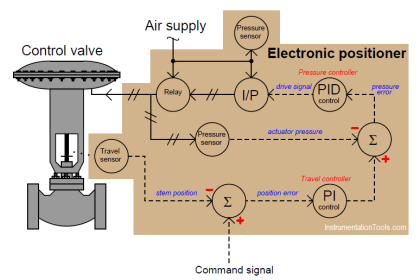
Architectures represented are based on the IEC 62443 Industrial Automation and Control Systems (IACS) architecture reference model. The basic model consists of 5 levels.

Contents
System ArchitectureLevel 0:Level 1:Level 2:Level 3:Level 4:Architecture Diagram Notations

System Architecture

Industrial Automation Architecture reference model

Figure 1: An Architecture reference model

Level 0:

It is the Process or equipment under control

Level 1:

It includes the Controllers/PLCs that provide basic control, safety and protection functions

Level 2:

It includes supervisory control functions and includes devices such as HMIs, Operating workstations, Engineering Workstations, Historians, Application Servers, Engineering Databases, etc.

Level 3:

It includes the operations management functions such as domain controller, backup server, antivirus and patch management, etc.

Level 4:

It refers to the Enterprise systems

Architecture Diagram Notations

  • The architecture diagrams show a very simplistic view of system architectures.
  • These architecture diagrams illustrate specific ways to perform remote access.
  • The local “IACS” network is represented simplistically to ease the understanding (the actual internal IACS architecture will vary and specific integration and interfaces between the diverse IACS usually required in most implementation is not included or represented in these diagrams).
  • Dataflows between the different functions are represented by arrows. The direction of the arrows show the outbound or inbound characteristic of the dataflow, but do not represent network sessions.
  • HMI is used as a generic term to refer to any Human Machine Interface or workstation (Operator, maintenance or engineering workstations, for BPCS, SIS, or Packages).
  • Local station refers to any workstation or server located at the production site that is used to transfer data or is accessed from a remote site.
  • The DMZ firewall is represented as a single symbol but can be implemented as a pair of physical firewalls.
  • The tunnel shown on the diagram refers to a secure tunnel, that can be set up with different technical solutions (e.g., IPSec).
  • These architecture Diagrams do not show the full detail of all possible types of local networks. Depending on the system vendor solution, some networks that are represented as the separate networks (such as control and HMI network) may be a single network.

Source: International Association of Oil & Gas Producers

Acknowledgments: IOGP Instrumentation and Automation Standards Subcommittee (IASSC) Remote Operating Centres Task Force.

Read Next:

  • Commissioning Documents
  • What is Process Control?
  • Cascade Control Loop Analysis
  • Direct Digital Control System
  • PID Controller Principle
Don't Miss Our Updates
Be the first to get exclusive content straight to your email.
We promise not to spam you. You can unsubscribe at any time.
Invalid email address
You've successfully subscribed !

Continue Reading

Distributed Control System Objective Questions
What is a Transducer ?
Relation Control System
What is Advanced Process Control (APC)?
Documentation and Change Control of PLC or DCS Systems
4-20 mA Transmitter Wiring Types : 2-Wire, 3-Wire, 4-Wire
Share This Article
Facebook Whatsapp Whatsapp LinkedIn Copy Link
Share
Leave a Comment

Leave a Reply Cancel reply

Your email address will not be published. Required fields are marked *

Stay Connected

128.3kFollowersLike
69.1kFollowersFollow
210kSubscribersSubscribe
38kFollowersFollow

Categories

Explore More

Process Dynamics and PID Controller Tuning
Compressor Emergency Shutdown Root Cause Analysis
What are Static UPS and Rotary UPS?
Analysis of HART communicator and Smart HART Transmitter
Hardwired I/O and Serial I/O – Differences Explained
Difference between Fieldbus, Profibus and HART Protocols
Integral Controller Principle
DCS Alarm Summary Dashboard using Microsoft Power BI

Keep Learning

Library of PlantPAx Process Objects

How to Download PlantPAx Library?

PID Controller Functions

PID Controller Functions

30 Concerns for Control System Philosophy (Industrial Automation)

30 Concerns for Process Control Systems Philosophy

PROFIBUS is also a Master Slave protocol

Compare Modbus, Fieldbus, and Profibus

Industry 4.0 Explained

Industry 4.0 Explained – Industrial Internet of Things

DeltaV Tune Tutorial

How to Tune a Loop in DeltaV System

Chart Recorders

What is a Recorder ?

Hot Well Level Control System in Condensing Turbine

Hot Well Level Control System in Condensing Turbine

Learn More

Flapper nozzle system

Flapper Nozzle Questions

Electric Motors Noises

Electric Motors Noises – Types, Possible Sources, Reasons

Pressure Gauge Functional Testing

Pressure Gauge Functional Testing

FIFO in STL Language in Siemens PLC

How to Code a FIFO Queue in STL Language in Siemens PLC?

How to Calibrate Load Cells

How to Calibrate Load Cells in Weighing Applications?

Shockley Diode Working Principle

Shockley Diode Working Principle

PID control block located in fieldbus transmitter

Foundation Fieldbus Device addressing

Pipeline Project Management

Pipeline Project Management

Menu

  • About
  • Privacy Policy
  • Copyright

Quick Links

  • Learn PLC
  • Helping Hand
  • Part Time Job

YouTube Subscribe

Follow US
All rights reserved. Reproduction in whole or in part without written permission is prohibited.
Welcome Back!

Sign in to your account

Username or Email Address
Password

Lost your password?