Proper installation and grounding of magnetic flowmeters is important for accurate, reliable measurement performance. Stray AC or DC currents through the fluid or instrument can produce noise signals that may in turn interfere with the relatively low flow signals generated in today’s modern pulsed DC magmeter.
Manufacturers provide a variety of elements (ground straps, ground electrodes, ground rings, lining protectors) and directions for the standard grounding of the magmeter.
Magnetic Flow Meters
Some Process conditions exist in which the user cannot or should not make use of the traditional grounding connection to adjacent piping and to earth ground. These flow measurement applications are frequently encountered in electrolytic processes and cathodic protection applications.
In this case, the fluid passing through the magmeter sensor may be at a potential significantly higher or lower than earth ground, and a connection to earth ground may be detrimental to the performance and even the reliability of the magmeter.
These applications are typically compounded by the use of non-conductive or lined pipe and may feature acid or caustic flows which may necessitate the use of expensive wetted electrodes and grounding materials such as titanium, platinum, or tantalum. Please refer to the section titled “Special Applications” for complete details regarding these special installation requirements
Magmeter Operating Principle
The operating principle of the magnetic flow meter is based on Faraday’s law of electromagnetic induction, which states that a voltage will be induced in a conductor moving through a magnetic field.
Faraday’s Law: E = kBDV
The magnitude of the induced voltage E is directly proportional to the velocity of the conductor V, conductor width D, and the strength of the magnetic field B.
The secondary (or transmitter) supplies the controlled current to the coils to generate the magnetic field, and amplifies, filters, and converts the resulting signal to user outputs such as 4 – 20 mA, frequency, or digital communication information (HART, FOUNDATION fieldbus, Profibus).
In the modern pulsed DC magmeter, the generated signal is actually quite small: typically on the order of 100 uV per foot per second flow velocity (300 uV per meter per second velocity).
Because this signal is so small, magmeter designers and users must take steps to minimize noise and maximize noise rejection. One of these steps is the proper grounding of the system.
Earth/Safety Grounding
To prevent hazards to operating personnel, electrical equipment must always be installed and wired per the local electrical code. For AC-powered equipment, this usually takes the form of a connection of the case of the equipment to earth ground.
This is usually done through the connection of the earthed green wire to the ground lug provided in the wiring area of the magmeter transmitter. If the transmitter is integrally mounted to the sensor, this automatically connects the sensor to earth ground as well.
It is common that the adjacent piping to the magmeter will provide a connection to Earth ground. A connection to Earth ground is also commonly made at the transmitter through the power connections.
It is important that if both Earth ground connections are established, the impedance between them must be very low. If the impedance between these earth-ground connections is high, it can result in a high current through the coil shield wire.
Basic Process Grounding
Establishing a process ground is one of the most important installation details. Proper process grounding ensures that the sensor and fluid are at the same potential so that only the induced flow signal is measured. Why is this necessary? To answer this question, lets look at how the magmeter sensor and the transmitter are connected electrically.
In a typical pulsed DC magmeter, the flow signal is connected to a differential amplifier that is electrically isolated from the case of the transmitter. The process of grounding provides a stable reference for this differential amplifier.
In the majority of applications, the best and most stable reference is earth ground itself. By connecting the magmeter sensor, the fluid, and the reference for the amplifier to a stable, noise free reference point, the user is ensured of getting the best performance from their magnetic flow meter.
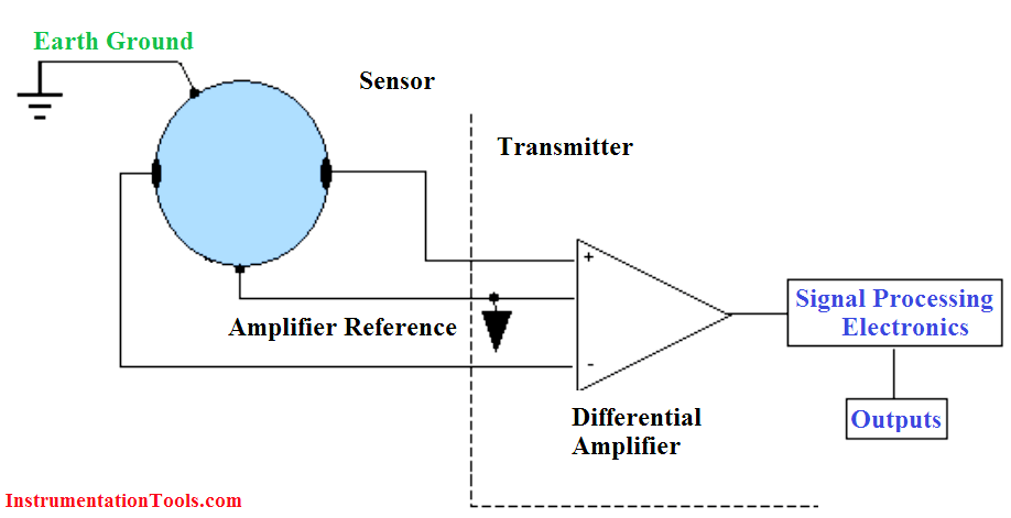
Figure 1. Basic electrical connection between sensor and transmitter
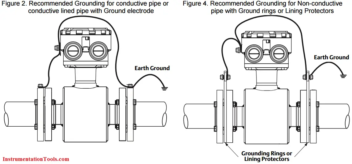
The grounding arrangement is determined primarily by the type of pipe in which the magmeter is installed.
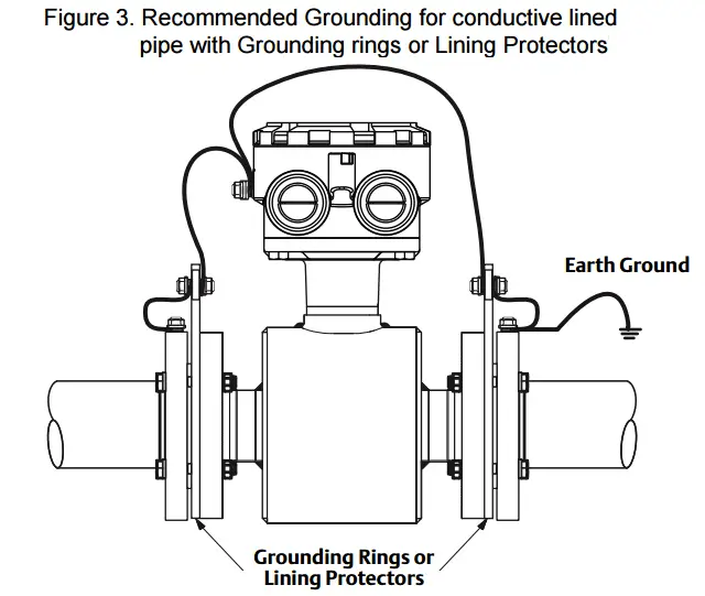
The recommended grounding arrangements for conductive unlined pipe, conductive lined pipe, and non-conductive pipe are shown in Figure 2 – Figure 4.
Ground Rings vs. Ground Electrode
As shown in the previous figures, ground rings or ground electrodes are required when the piping adjacent to the magmeter does not provide a good electrical connection to the fluid; i.e., the pipe is lined or made of non-conductive material.
Ground rings or a ground electrode provide the required electrical connection to the process fluid. Ground electrodes are integral to the sensor, so installation is easier and less expensive, particularly when “exotic” materials are required.
Ground rings provide a larger surface area connection to the process fluid, and limit the effects of the conductivity of the adjacent piping, which is important for wafer style sensors. Therefore ground rings are recommended over a ground electrode in the following situations:
- The fluid conductivity is less than 100uS/cm
- Wafer style sensors installed in non-conductive piping or lined piping
- Applications that may cause a coating or build-up on the bottom of the pipe
- Electrolytic process or cathodic protection applications
SPECIAL APPLICATIONS
Electrolytic Process Applications
In typical electrolytic processes, magmeters are used to measure the flow of feedstock fluids into the cell(s). Large DC currents (1000’s of amps or higher) are fed into the cells to drive the electrolytic process. The resultant liquids and gasses may also be monitored by additional flow meters.
The electrolytic process may occur in one reactor or very many cells. In the latter case, each cell may have its own magmeter for feedstock flow measurement.
Whatever the arrangement, the large voltages and currents present may cause currents to flow in unexpected ways. The current flows of interest here are generally of two types:
- Current flow in the fluid through the magmeter
- Current flow through grounding components
Both types of current may be present in a typical application of these types. In the first case, the flow of current in the fluid passing through the sensor generates noise that may interfere with the low-level flow signal. Testing indicates that this noise varies with current level and has components that can easily interfere with the flow signal.
The result is usually not an inaccurate flow measurement, but rather an unstable flow measurement that can make control difficult or impossible. In this situation, ground rings provide a path to shunt the current around the fluid in the magmeter.
Current flow through grounding components may occur if:
- multiple magmeters are used in a system;
- they are at different potentials and;
3. the grounding components for multiple magmeters are tied to a common point. The most frequent common point may be through the grounded green wire. Situations like this have resulted in high corrosion of grounding components, up to and including the loss of sealing around a ground electrode.
In addition, current through grounding components generates noise that can result in an unstable magmeter output.
Recommendations for Electrolytic Process Applications
1. Isolate from Earth Ground: In these situations, the magmeter should be connected electrically only to the process. Because the magmeter is not earth grounded, isolated DC power (~24 VDC) should be used to avoid safety issues. If isolated DC power is not available, then the transmitter will have to be remotely mounted from the sensor. Always follow all applicable national and local safety codes.
2. Use ground rings or lining protectors, not ground electrode: Ground rings expose more surface to the process; if currents flow, less noise will be produced, providing a more stable reference for the amplifier. Using two ground rings will provide a path to shunt the current around the fluid in the magmeter.
3. Connection specifics: Ground rings or lining protectors should be connected as shown in Figure 5. It is very important to connect both ground rings to the sensor case to minimize the current flow through the process fluid near the electrodes.
4. Select 37 Hz coil drive frequency: The noise generated in these applications typically has a 1/f characteristic; i.e., the amplitude of the noise decreases with increasing frequency. Because of this characteristic, there is less noise at a higher coil drive frequency, and a more stable output is attained.
Cathodic Protection Applications
Cathodic protection is a technique used to limit the corrosion of a metal surface by making it the cathode in an electrochemical cell. Another piece of more easily corroded metal becomes the anode in the electrochemical cell. In long pipelines a large DC current is run through the process fluid to drive the cathodic protection.
It is important that only the anode has a connection to earth ground in these applications. If another earth ground connection is present it may also provide the anodic material for the cathodic protection system. Therefore all piping and instrumentation, including magmeters, must be isolated from earth ground.
Recommendations for Cathodic Protection
1. Isolate from Earth Ground: In these situations, the magmeter should be connected electrically only to the process. Because the magmeter is not earth grounded, isolated DC power (~24 VDC) should be used to avoid safety issues. If isolated DC power is not available, then the transmitter will have to be remotely mounted from the sensor. Always follow all applicable national and local safety codes.
2. Use ground rings or lining protectors, not ground electrode: Ground rings expose more surface to the process; if currents flow, less noise will be produced, providing a more stable reference for the amplifier. Using two ground rings will provide a path to shunt the current around the fluid in the magmeter.
3. Connection specifics: Ground rings or lining protectors should be connected as shown in Figure 5. It is very important to connect both ground rings to the sensor case to minimize the current flow through the process fluid near the electrodes.
4. Special Differential Amplifier: In some installations, the transmitter output may be driven to 0 even though there is flow in the pipe. This is caused by the DC voltage of the cathodic protection system interfering with the operation of the standard differential amplifier in the electrode signal circuitry of the transmitter. If this situation occurs, a new transmitter with special option should be installed or replaced with existing one.
Conclusion
Proper grounding of a magmeter is one of the most important installation details. Grounding arrangements for typical applications have been discussed, including recommendations for the use of ground electrodes versus ground rings.
Different grounding arrangements are required when magmeters are installed in electrolytic process and cathodic protection applications where the traditional connection to earth ground could actually create problems.
While this paper provides general recommendations for these applications, each application is different. Electrolytic processes and cathodic protection applications can create special safety considerations for all equipment, not just the magnetic flowmeters
Article Source: Rosemount
If you liked this article, then please subscribe to our YouTube Channel for Instrumentation, Electrical, PLC, and SCADA video tutorials.
You can also follow us on Facebook and Twitter to receive daily updates.
Read Next:
- Orifice Flow Meter Theory
- Flow Sensors Questions
- Invasive Flow Instruments
- Flow Meter Accuracy
- Hot Wire Anemometer
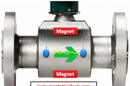


Fig 2
Its recommended to weld the Earth Connection to the pipe insted to connect it to the flange.
In case there is painted flanges or oxide you could have a bad grounding Connection.
Dear viewers,
I had faced one miscellaneous problem with magnetic 4 wire flowmeter.mA is coming from flowmeter which is connected to Analog input card and that flow meter range is 0 to 1000mmhg and that card channal also configured range as 0 to 1000mmhg from flowmeter 12mA is coming in SCADA has to show 500mmhg but its showing 56mmhg then i removed flowmeter mA cable in card and then i Sourced externally 12mA to the input card in scada its showing 500mhg.then i confirmed there is a problem with flowmeter.what would be the problem.and how to rectify it.pls rply
Flow meter make:E&H promag10
Hi,
Major problem with mag flowmeters comes with improper grounding, so check your flow meter ground healthy status.
And what is the output current from flow meter ? Isolate from PLC/DCS and check your output current ?
hi,
Flowmeter grounding is very healthy and Flowmeter output current is achieving as per flowrate.flow meter range is 0 to 1000kg/cm2. at 500kg/cm2 flowrate 12mA is achieving.
Okay, Then check the flow meter output current in series with the PLC/DCS, If output current found normal then connect the flow meter to another Analog Input card spare channel and observe the readings (for checking purpose).
hi,
same think i checked i connected to another channel also still showing error reading.and then i changed module also still same error coming.
Hi
mA is coming but card not taking .
After we changed E&H make another flow meter now it is working properly.
there is problem with flow meter only.
But we could’t identify the problem..