Inst ToolsInst ToolsInst Tools
  • Courses
  • Automation
    • PLC
    • Control System
    • Safety System
    • Communication
    • Fire & Gas System
  • Instrumentation
    • Design
    • Pressure
    • Temperature
    • Flow
    • Level
    • Vibration
    • Analyzer
    • Control Valve
    • Switch
    • Calibration
    • Erection & Commissioning
  • Interview
    • Instrumentation
    • Electrical
    • Electronics
    • Practical
  • Q&A
    • Instrumentation
    • Control System
    • Electrical
    • Electronics
    • Analog Electronics
    • Digital Electronics
    • Power Electronics
    • Microprocessor
  • Request
Search
  • Books
  • Software
  • Projects
  • Process
  • Tools
  • Basics
  • Formula
  • Power Plant
  • Root Cause Analysis
  • Electrical Basics
  • Animation
  • Standards
  • 4-20 mA Course
  • Siemens PLC Course
Reading: Impedance
Share
Font ResizerAa
Inst ToolsInst Tools
Font ResizerAa
  • Courses
  • Design
  • PLC
  • Interview
  • Control System
Search
  • Courses
  • Automation
    • PLC
    • Control System
    • Safety System
    • Communication
    • Fire & Gas System
  • Instrumentation
    • Design
    • Pressure
    • Temperature
    • Flow
    • Level
    • Vibration
    • Analyzer
    • Control Valve
    • Switch
    • Calibration
    • Erection & Commissioning
  • Interview
    • Instrumentation
    • Electrical
    • Electronics
    • Practical
  • Q&A
    • Instrumentation
    • Control System
    • Electrical
    • Electronics
    • Analog Electronics
    • Digital Electronics
    • Power Electronics
    • Microprocessor
  • Request
Follow US
All rights reserved. Reproduction in whole or in part without written permission is prohibited.
Inst Tools > Blog > Electrical Theory > Impedance

Impedance

Last updated: July 30, 2018 7:33 pm
Editorial Staff
Electrical Theory
No Comments
Share
3 Min Read
SHARE

Whenever inductive and capacitive components are used in an AC circuit, the calculation of their effects on the flow of current is important.

Impedance

No circuit is without some resistance, whether desired or not. Resistive and reactive components in an AC circuit oppose current flow. The total opposition to current flow in a circuit depends on its resistance, its reactance, and the phase relationships between them.

Impedance is defined as the total opposition to current flow in a circuit.

The below Equation is the mathematical representation for the magnitude of impedance in an AC circuit.
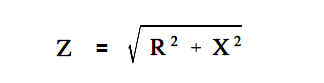
Impedance equation

where
Z = impedance (Ω)
R = resistance (Ω)
X = net reactance (Ω)

The relationship between resistance, reactance, and impedance is shown in Figure 5.

relationship between resistance, reactance, and impedance

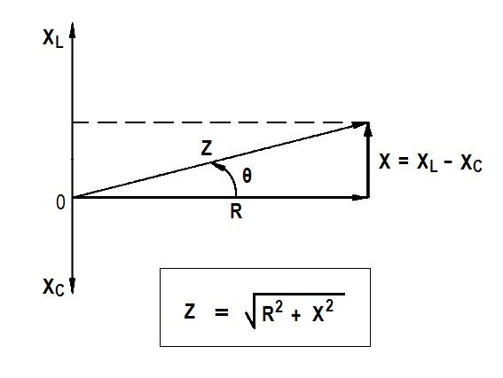
Figure 5 : Relationship Between Resistance, Reactance, and Impedance

The current through a certain resistance is always in phase with the applied voltage. Resistance is shown on the zero axis. The current through an inductor lags applied voltage by 90°; inductive reactance is shown along the 90° axis. Current through a capacitor leads applied voltage by 90°; capacitive reactance is shown along the -90° axis. Net reactance in an AC circuit is the difference between inductive and capacitive reactance.

The below Equation is the mathematical representation for the calculation of net reactance when XL is greater than XC.

X = XL – XC

where

X = net reactance (Ω)
XL = inductive reactance (Ω)
XC = capacitive reactance (Ω)

The below Equation is the mathematical representation for the calculation of net reactance when XC is greater than XL.

X = XC – XL

Impedance is the vector sum of the resistance and net reactance (X) in a circuit, as shown in Figure 5. The angle θ is the phase angle and gives the phase relationship between the applied voltage and the current. Impedance in an AC circuit corresponds to the resistance of a DC circuit. The voltage drop across an AC circuit element equals the current times the impedance.

The below Equation is the mathematical representation of the voltage drop across an AC circuit.

V = IZ

where

V = voltage drop (V)
I = current (A)
Z = impedance (Ω)

The phase angle θ gives the phase relationship between current and the voltage.

Don't Miss Our Updates
Be the first to get exclusive content straight to your email.
We promise not to spam you. You can unsubscribe at any time.
Invalid email address
You've successfully subscribed !

Continue Reading

DC Motor Speed
Magnetic Circuits
Wiring Diagram
High Voltage Circuit Breaker Principle
Electrical Diagrams and Schematics
DC Machines Construction
Share This Article
Facebook Whatsapp Whatsapp LinkedIn Copy Link
Share
Leave a Comment

Leave a Reply Cancel reply

Your email address will not be published. Required fields are marked *

Stay Connected

128.3kFollowersLike
69.1kFollowersFollow
210kSubscribersSubscribe
38kFollowersFollow

Categories

Explore More

DC Generator Internal Losses
How to Measure Specific Gravity of Battery
D’Arsonval Meter Movement
Electrical System Components and Protection Devices
DC Generator Theory
Synchronous Motors
Applying Kirchhoff’s Current Law
Parallel Circuit Current Calculations

Keep Learning

Starting a Synchronous Motor

Starting a Synchronous Motor

Voltage Polarities

Voltage Polarity and Current Direction

Cutaway View of Circuit Breaker

Low Voltage Air Circuit Breaker Principle

Megger Circuit Diagram

Multimeter & Megger Principle

Half-Wave Rectifier Circuit

Half-Wave Rectifier Circuit

Left-Hand Rule for Generators

Starting of DC Motors

Battery Interview QuBattery Interview Question and Answersestion and Answers

Battery Terminology

Gang Switch Principle

Reading Electrical Schematics

Learn More

IEC 61508

What is IEC 61508 ?

PLC Karnaugh maps

How to Simplify PLC Coding Using Karnaugh Maps?

Block Diagram

Block Diagram

Differential Pressure Flow Transmitter Interview Questions

Interview Questions on Differential Pressure Flow Transmitter

Modbus scan

How Modbus Communication works

Top 10 Facts about HART Technology

What is HART, Foundation Fieldbus & Profibus ?

Relay Wiring

Animation of Electromagnetic Relay

OPC Server

What is the OPC Server?

Menu

  • About
  • Privacy Policy
  • Copyright

Quick Links

  • Learn PLC
  • Helping Hand
  • Part Time Job

YouTube Subscribe

Follow US
All rights reserved. Reproduction in whole or in part without written permission is prohibited.
Welcome Back!

Sign in to your account

Username or Email Address
Password

Lost your password?