Inst ToolsInst ToolsInst Tools
  • Courses
  • Automation
    • PLC
    • Control System
    • Safety System
    • Communication
    • Fire & Gas System
  • Instrumentation
    • Design
    • Pressure
    • Temperature
    • Flow
    • Level
    • Vibration
    • Analyzer
    • Control Valve
    • Switch
    • Calibration
    • Erection & Commissioning
  • Interview
    • Instrumentation
    • Electrical
    • Electronics
    • Practical
  • Q&A
    • Instrumentation
    • Control System
    • Electrical
    • Electronics
    • Analog Electronics
    • Digital Electronics
    • Power Electronics
    • Microprocessor
  • Request
Search
  • Books
  • Software
  • Projects
  • Process
  • Tools
  • Basics
  • Formula
  • Power Plant
  • Root Cause Analysis
  • Electrical Basics
  • Animation
  • Standards
  • 4-20 mA Course
  • Siemens PLC Course
Reading: Identify Instruments in Piping and instrumentation Diagram
Share
Font ResizerAa
Inst ToolsInst Tools
Font ResizerAa
  • Courses
  • Design
  • PLC
  • Interview
  • Control System
Search
  • Courses
  • Automation
    • PLC
    • Control System
    • Safety System
    • Communication
    • Fire & Gas System
  • Instrumentation
    • Design
    • Pressure
    • Temperature
    • Flow
    • Level
    • Vibration
    • Analyzer
    • Control Valve
    • Switch
    • Calibration
    • Erection & Commissioning
  • Interview
    • Instrumentation
    • Electrical
    • Electronics
    • Practical
  • Q&A
    • Instrumentation
    • Control System
    • Electrical
    • Electronics
    • Analog Electronics
    • Digital Electronics
    • Power Electronics
    • Microprocessor
  • Request
Follow US
All rights reserved. Reproduction in whole or in part without written permission is prohibited.
Inst Tools > Blog > Control Systems > Identify Instruments in Piping and instrumentation Diagram

Identify Instruments in Piping and instrumentation Diagram

Last updated: January 10, 2020 9:26 am
Editorial Staff
Control Systems
1 Comment
Share
0 Min Read
SHARE

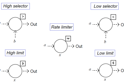
Identify the meanings of the following instruments in this Piping and instrumentation Diagram (P&ID).

Contents
Piping and instrumentation DiagramSolution:

Piping and instrumentation Diagram

Identify Instruments in Piping and instrumentation Diagram

Solution:

The below Piping and instrumentation (P&ID) Diagram shows the abbreviations or meaning of the instrument symbols.

Piping and instrumentation Diagram Abbreviations

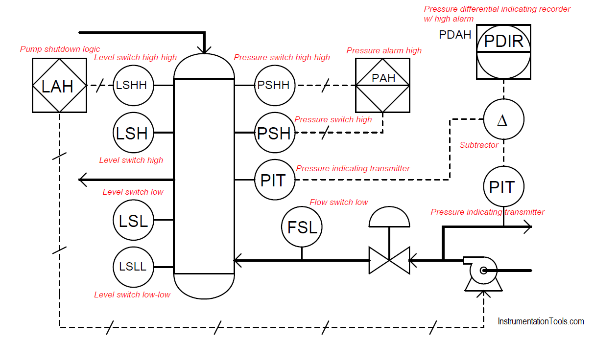
Credits: Tony R. Kuphaldt

Read Next:

  • Architecture of Instrumentation
  • Control loop in P&ID
  • Instrumentation Symbols Legend
  • Schematic Diagram
  • Industrial Instrumentation Quiz
  • 100 PLC Quiz Questions
Don't Miss Our Updates
Be the first to get exclusive content straight to your email.
We promise not to spam you. You can unsubscribe at any time.
Invalid email address
You've successfully subscribed !

Continue Reading

Stroke Checking Procedure for GCV, SRV, IGV, and LFBV
Managed Switch vs Unmanaged Switch
Integrating Processes – Liquid Level Control
Emergency Stop Switch Spurious Trip
Pressure Control Loop Wiring Connections
Loop Calibrator to Simulate a 4-20 mA Signal
Share This Article
Facebook Whatsapp Whatsapp LinkedIn Copy Link
Share
1 Comment
  • Leo Salemi says:
    April 12, 2024 at 6:41 pm

    No mention of what the difference between a Piping and Instrumentation Drawing vs Process and Instrumentation Drawing vs Process Flow Drawing
    No mention about the ISA 5.1 standard for P&ID symbols
    No mention of what a round instrument located in a square is.

    Other than that, its a good video.

    Reply

Leave a Reply Cancel reply

Your email address will not be published. Required fields are marked *

Stay Connected

128.3kFollowersLike
69.1kFollowersFollow
210kSubscribersSubscribe
38kFollowersFollow

Categories

Explore More

Industrial Automation in the Mining Industry
What is Alarm Management System ?
How to Create a Project in LabVIEW?
Loop Controller HART Signal Noise
What is Wellhead Control Panel?
Node-RED in PLC Industrial Automation
I&C Engineer Roles & Responsibilities – Instrumentation Design
What is Instrumentation and Control ?

Keep Learning

Override Control Functions

Override Control Functions

Zener Barrier Protection

Zener Diode Barrier Principle

Pressure and Level Control Loop

Problem on Pressure and Level Control Loops

power factor correction equipment

Power Factor Controller (PFC) – Commissioning

Control Loops

Control Loops Objective Questions and Answers

Grounding or Earthing Scheme in DCS or PLC Systems

Grounding or Earthing Scheme in DCS or PLC Systems

Process Control Automation PLC Quiz

Process Control Automation PLC Quiz

Distributed Control System & Motor Control Center Interface Philosophy

Distributed Control System & Motor Control Center Interface Philosophy

Learn More

Power Electronics Objective Questions

Half Wave Diode Rectifier Quiz

testing-thermocouples-and-rtds

Testing thermocouples and RTDs using Multi-function Calibrators

Proportional Control Theory

Proportional-only Offset

Oil in Water Analyzer Principle

Oil in Water Analyzer Working Principle

Basic Transistor Amplifier Circuit Principle

Basic Transistor Amplifier Circuit Principle

Power Electronics Objective Questions

MOSFET Objective Questions

Boiler-Drum-Level-transmitter-calibration

Boiler Drum Level Transmitter Calibration

Motor Feedback Fail Logic in PLC

Motor Feedback Fail Logic in PLC

Menu

  • About
  • Privacy Policy
  • Copyright

Quick Links

  • Learn PLC
  • Helping Hand
  • Part Time Job

YouTube Subscribe

Follow US
All rights reserved. Reproduction in whole or in part without written permission is prohibited.
Welcome Back!

Sign in to your account

Username or Email Address
Password

Lost your password?