This is complete tutorial of weigh feeder definition, principle and working.
This tutorial is all about weigh feeder.
- What is weigh feeder?
- Instruments used with weigh feeder.
- How do they work with each other?
What is Weigh feeder?
Movement of bulk material with precise weighing and at a fast speed is the key role in process industries.
The simplest form of bulk material transportation is to convey them over a moving belt and it is necessary to weigh a moving bulk material accurately to control the process as per requirement.
Weigh feeder is a closed-loop control system, which controls the flow of material very accurately using controller and different instruments. This system accepts an external command from process computers like SCADA, HMI, DCS etc.
This type of weigh feeder used in industries like Steel Plant, Cement Plant, Fertilizer and Chemical industries.
The instrument used in this system to control the flow rate is Closed-loop control with panels, Load cell to measure the weight of a predefined area on the belt and Encoder to measure the speed of the belt, AC Drive to control the speed of the motor which is connected on the gear box to drive the conveyor belt.
Instruments used in weigh feeder system
- Closed-loop controller
- Load cell
- Tacho
- AC Drive
Closed-loop Controller :
The closed-loop controller is a micro controller-based instrument which can be programmed according to user requirement. Basically, it gets signals from load cell and encoder, these two signals are converted according to field instrument rating and then multiplied together to get the current rate of flow.
This rate of flow is used to control the set flow which is given in the controller by using external controller or process computer. Also, there is a facility to generate the alarm or error if field environment is outside the given parameter.
The controller accepts a set flow rate via electrical signal which is 4-20 mA and also give an output flow rate is the same electrical signal. Controller also gives an electrical signal to control the speed of the motor through the AC drive according to set flow rate.
Load cell :
A load cell is a force transducer, which converts force or load into electrical signal. The main element of the load cell is strain gauge.
A strain gauge changes its resistance with the applied force on it, which is made with the ultra-thin heat-treated metallic foil chemically bonded to a thin dielectric layer.
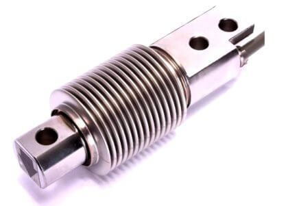
There are normally four strain gauges that are bonded in the Wheatstone bridge configuration. The input supply to the load cell is in Volts and also known as excitation voltage. The output of the load cell is in mili Volts.
Tacho :
The speed of the belt is measured with tacho generator which is driven by the return belt.
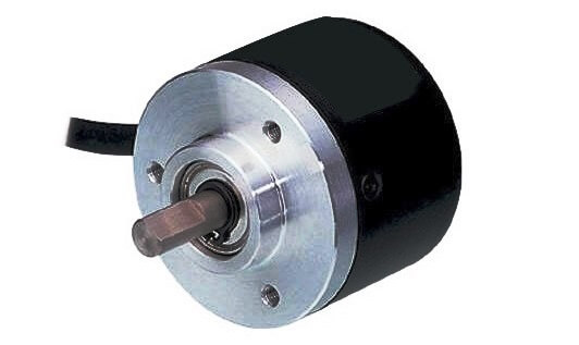
This consists of a proximity type speed sensor, which is triggered by a disc mounted inside the tacho generator. Generally, the input of this sensor is in Volts and the output is in frequency with fixed amplitude.
AC Drive :
AC Drive is used to vary the speed of the motor and often called as variable frequency drive. The operation of VFD is very simple.
Basically, First AC input voltage and frequency is converted to DC voltage using rectifiers.
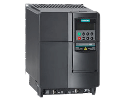
Then this DC voltage is converted back to AC voltage using inverter. This output AC voltage and frequency is the desired output which meets the volts per hertz ratio.
How weigh feeder works ?
The below pictures shows the basic diagram of weigh feeder system.
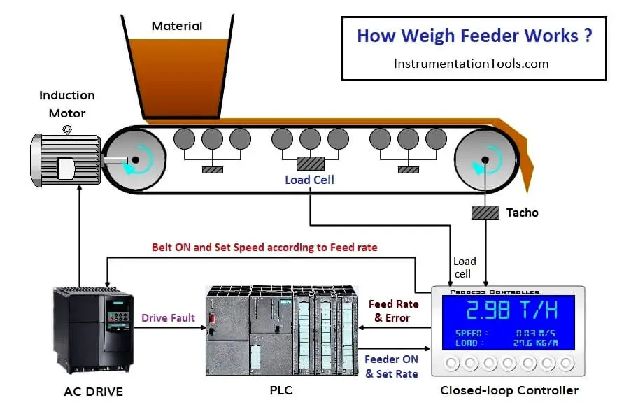
So, let’s see the steps how this system works –
- Check the ready signal, If all the instruments and devices are ready then you will get ready signal otherwise check for error.
- As soon as system is ready, Operator can give start command to start the system. PLC give Feeder ON command to controller.
- After getting Feeder ON command from PLC, Controller gives a Belt ON command to start the AC drive.
- Belt starts rotating as soon as AC drive starts, if there is an error then drive doesn’t give run feedback to PLC and PLC reset its Feeder ON command to controller and generate error. If there is no fault then AC Drive gives Run Feedback to PLC.
- Now controller gets feedback from load cell and Tacho. Load is in kg/m and Tacho gives speed in m/s. Both the feedback will be multiplied and we will get a flow rate which is in t/h. That will transfer to PLC.
- Controller also gets the set flow rate from PLC, this set rate and current flow rate is continuously compared with each other and set speed command is issued according to PID setting to AC drive.
- As set rate is greater than current flow rate then speed is increased and if current flow rate is greater than set rate then speed is decreased.
If you liked this article, then please subscribe to our YouTube Channel for PLC and SCADA video tutorials.
You can also follow us on Facebook and Twitter to receive daily updates.
Read Next:




Excellent Information, Thanks
Not the detail I was hoping for. As described, it works great if the flow rate is continuous. Was hoping the article would describe a system that could handle an inconsistent feed
Very educative information. Thanks
Very educative information,at least I have learn something, thank you
Is it possible to apply this procedure without closed loop controller? So, all of the calculations (Loadcell & Tacho) and comparation (Set rate & Current flow rate) just on PLC. Thank you.
yes, sure you can.
Flow(T/H)=0.03 * speed
Why to use in weigh feeder in two load cells?
Why to use in weigh feeder two load cells?
What happened if weighfeeder weghing idler worn out