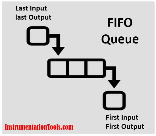
Welcome back Automation seekers in the last post we have learned how to create a FIFO register using Siemens ready-made functions in TIA Portal.
FIFO in STL Language
Today we are going to make the same task (FIFO Register), but in a different way, as we will code the function itself so if you are interested in programming here is another technical method to build FIFO (First in First Out) register.
Example Code in STL
Here we have a situation that requires storing some transmitter readings (20, 26, 19, 22, ….) every reading should be handled in its turn as whenever it is needed it will also be presented in its turn.
So, in order to avoid repeated coding and routine programming we are going to make a Hand-Made function block that would allow us to create the FIFO queue.
Step (1): Creating the function block
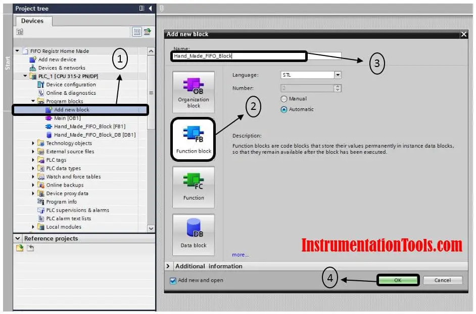
First of all, we will create an ordinary Function Block (automatically it will create an instance data block for itself). As shown in Fig. (1)
Step (2): Defining Inputs & Outputs of function
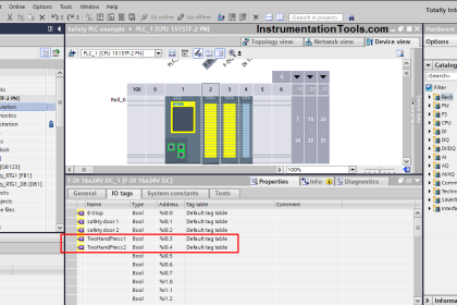
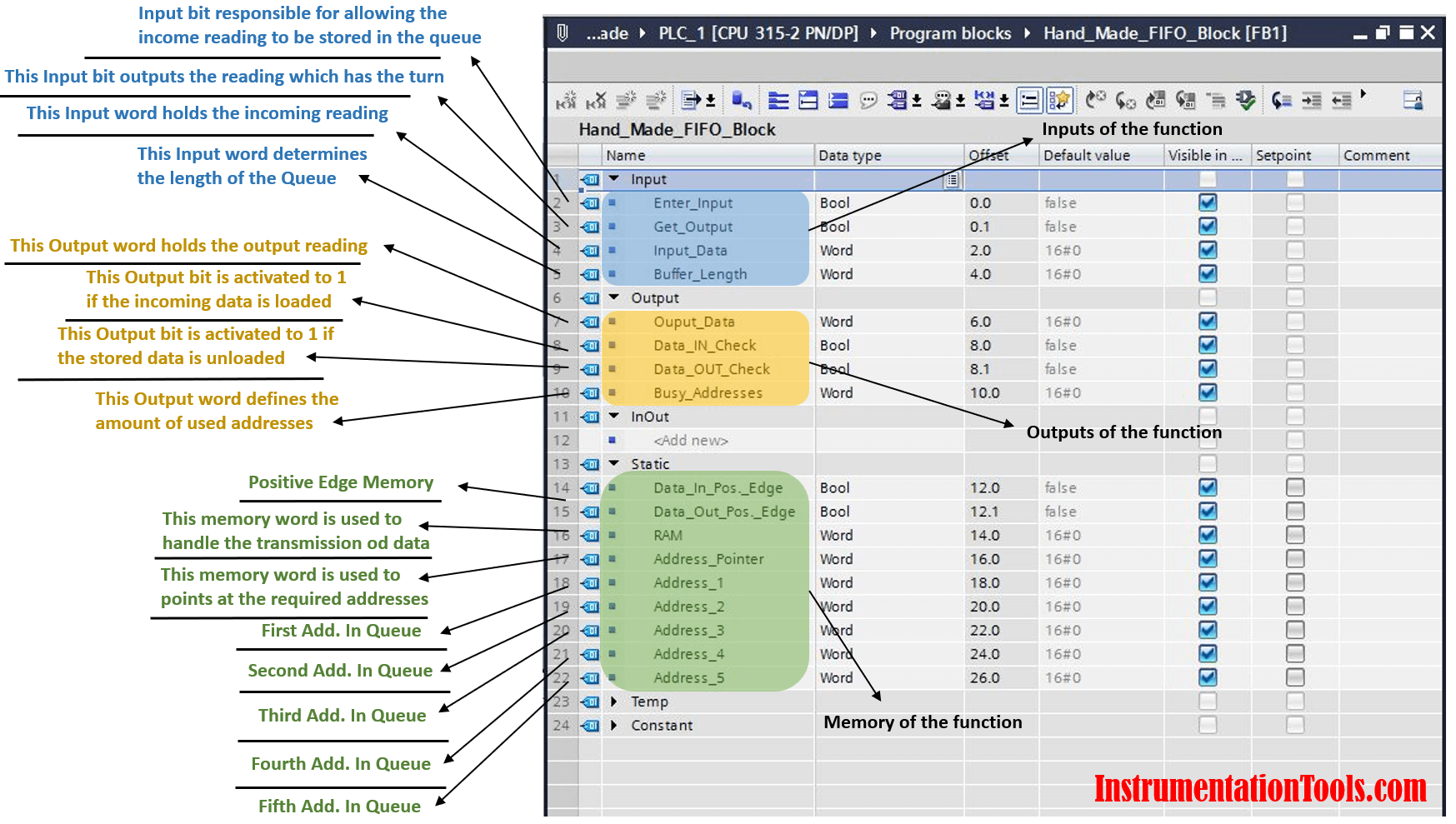
As we can see in the next figure Fig. (2), we defined our inputs, output, and the variables that will be stored in the instance database memory.
Step (3): Coding of the FIFO Queue
And now let us put some coding into the function block that we have created.
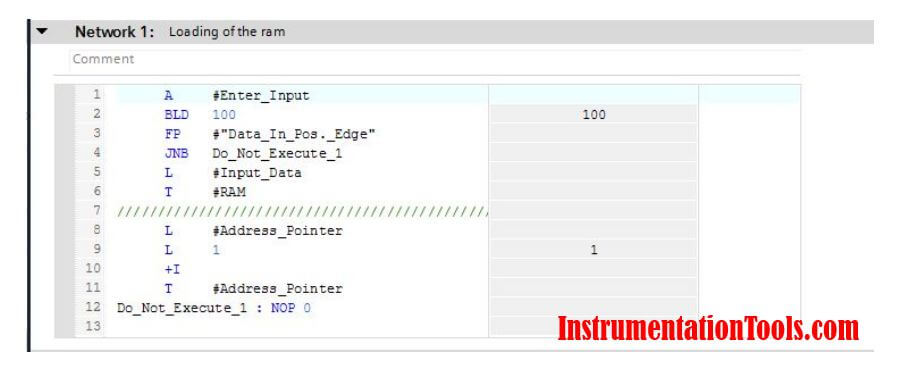
Here for the first network as we can see in Fig. (3) IF the bit “Enter_Input” is activated the program will detect the input data and it will copy it to the word “RAM” to be stored in its turn.
After that we increased the “Address_Pointer” by one, this address pointer will help us to put the data in its turn in the queue as we will see.
And IF the bit “Enter_Input” is not activated the program will escape this instruction.
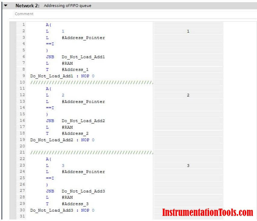
As we said before the Address pointer helps us to organize the incoming readings so in Fig. (4) we can see that if the Address pointer = 1 (the incoming reading will be saved into the first address).
And if the Address pointer = (the incoming reading will be saved into the second address) … etc.
So, as we noticed the incoming readings would never be stored with the same address because of the Address Pointer.
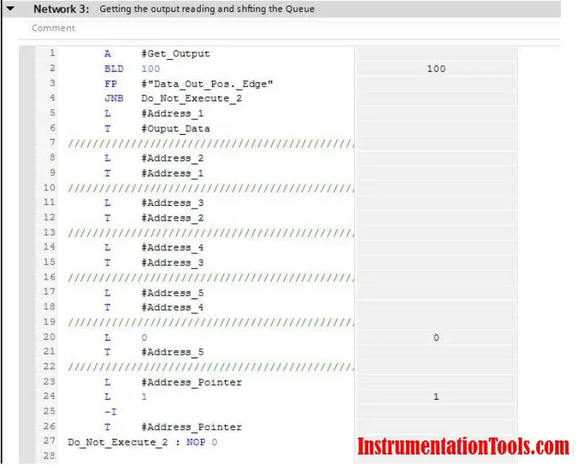
Here for this network that is shown in Fig. (5) IF the bit “Get_Output” is activated the program will select the reading that it is in turn (First Address) and the program will copy it to the function output word (Outcome).
After that, the program will make a shifting operation for the addresses as the content of Address (2) will be stored into Address (1) and the same for Addresses (3,2) and the same for all other addresses.
We can describe this instruction exactly as the Queue moving.
Finally, we will decrease the Address Pointer by one to let the program knows that the queue gets rid of the first reading.
Download the code: FIFO Block in STL
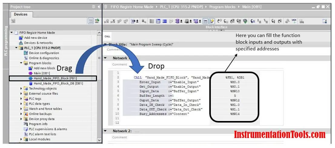
Step (4): Calling the Function Block into the Main OB
As all of us know the program will not execute this function until you call it in the Main OB because the scan cycle of Siemens PLCs starts with the Main OB.
So here in Fig. (6), all we need to do is to drag and drop the Function Block at the first network.
Then put the desired address for your block.
Video
If you liked this article, then please subscribe to our YouTube Channel for Electrical, Electronics, Instrumentation, PLC, and SCADA video tutorials.
You can also follow us on Facebook and Twitter to receive daily updates.
Read Next:
- What is a Wet Contact?
- Preventive Maintenance of VFD
- Why 24 Volts DC Power Supply?
- Commissioning and Testing of PLC
- Automation Engineer Troubleshooting