Inst ToolsInst ToolsInst Tools
  • Courses
  • Automation
    • PLC
    • Control System
    • Safety System
    • Communication
    • Fire & Gas System
  • Instrumentation
    • Design
    • Pressure
    • Temperature
    • Flow
    • Level
    • Vibration
    • Analyzer
    • Control Valve
    • Switch
    • Calibration
    • Erection & Commissioning
  • Interview
    • Instrumentation
    • Electrical
    • Electronics
    • Practical
  • Q&A
    • Instrumentation
    • Control System
    • Electrical
    • Electronics
    • Analog Electronics
    • Digital Electronics
    • Power Electronics
    • Microprocessor
  • Request
Search
  • Books
  • Software
  • Projects
  • Process
  • Tools
  • Basics
  • Formula
  • Power Plant
  • Root Cause Analysis
  • Electrical Basics
  • Animation
  • Standards
  • 4-20 mA Course
  • Siemens PLC Course
Reading: HMI Screen Design for Hazardous Applications
Share
Notification Show More
Font ResizerAa
Inst ToolsInst Tools
Font ResizerAa
  • Courses
  • Design
  • PLC
  • Interview
  • Control System
Search
  • Courses
  • Automation
    • PLC
    • Control System
    • Safety System
    • Communication
    • Fire & Gas System
  • Instrumentation
    • Design
    • Pressure
    • Temperature
    • Flow
    • Level
    • Vibration
    • Analyzer
    • Control Valve
    • Switch
    • Calibration
    • Erection & Commissioning
  • Interview
    • Instrumentation
    • Electrical
    • Electronics
    • Practical
  • Q&A
    • Instrumentation
    • Control System
    • Electrical
    • Electronics
    • Analog Electronics
    • Digital Electronics
    • Power Electronics
    • Microprocessor
  • Request
Follow US
All rights reserved. Reproduction in whole or in part without written permission is prohibited.
Inst Tools > Blog > PLC Tutorials > HMI Screen Design for Hazardous Applications

HMI Screen Design for Hazardous Applications

In this article, we will learn the design standards to consider for HMI screen design in hazardous areas with PLC applications.

Last updated: May 23, 2023 11:11 am
Viral Nagda
PLC Tutorials
No Comments
Share
5 Min Read
SHARE

Industrial automation is majorly divided into two types of categories in terms of safety – hazardous and non-hazardous. Hazardous applications, as the name implies, regard a lot in terms of worker safety, environment safety, operational hazards, and machine safety.

So, it is most important to deal properly with them; because not only application constraints, but hazardous applications also deal with safety constraints. When you use graphical displays like HMI in a hazardous application, utmost care must be taken to design them efficiently.

Siemens Simatic HMI

This is because improper navigation and symbols can take a lot of time for the operator to troubleshoot, and this can badly hamper the maintenance and commissioning activities. In the worst case, if it is not handled properly and attended to on time, then it can even cause damage to human life.

In this article, we will learn the design standards to consider for HMI screen design in hazardous areas with PLC applications.

HMI Screen Design for Hazardous Applications

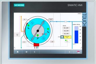
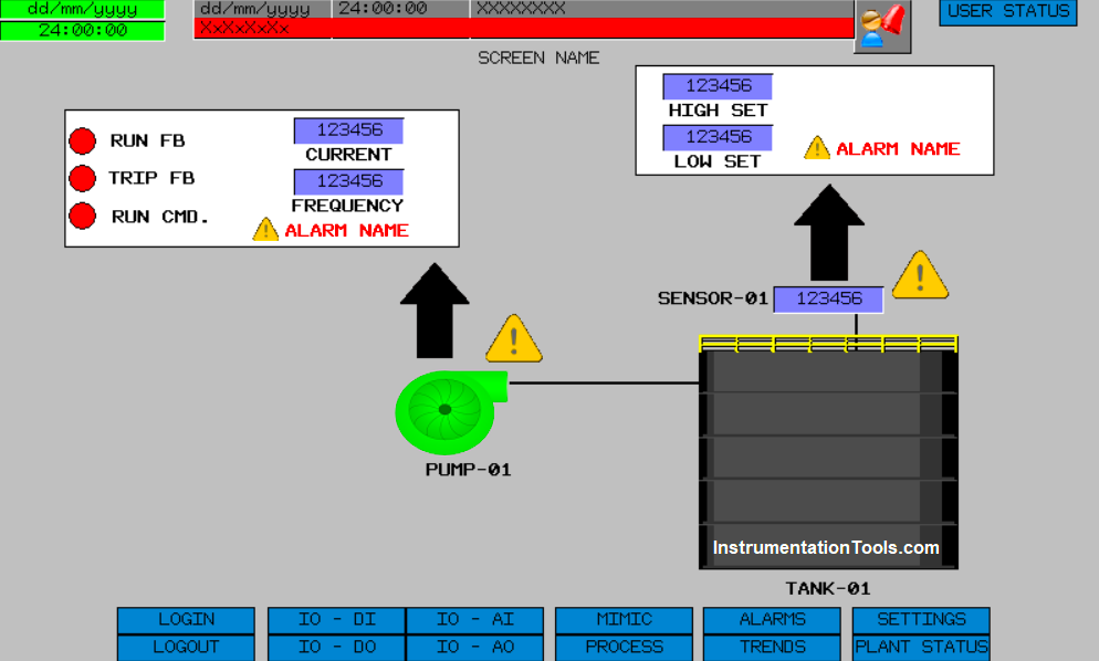
The first step in designing HMI is taking care of the header and footer. An operator will always require quick access to the processes, diagnostics, and settings. So, if you give all the necessary buttons in the header and footer, then the operator can easily go to any screen in a quick time.

In the below image, you can see that all the important buttons, which will be used in the whole HMI navigation, like – user status, login, logout, IO status, mimic view, process selection, alarms, trends, settings, and plant status; are shown in the header and footer.

Basic HMI Screen

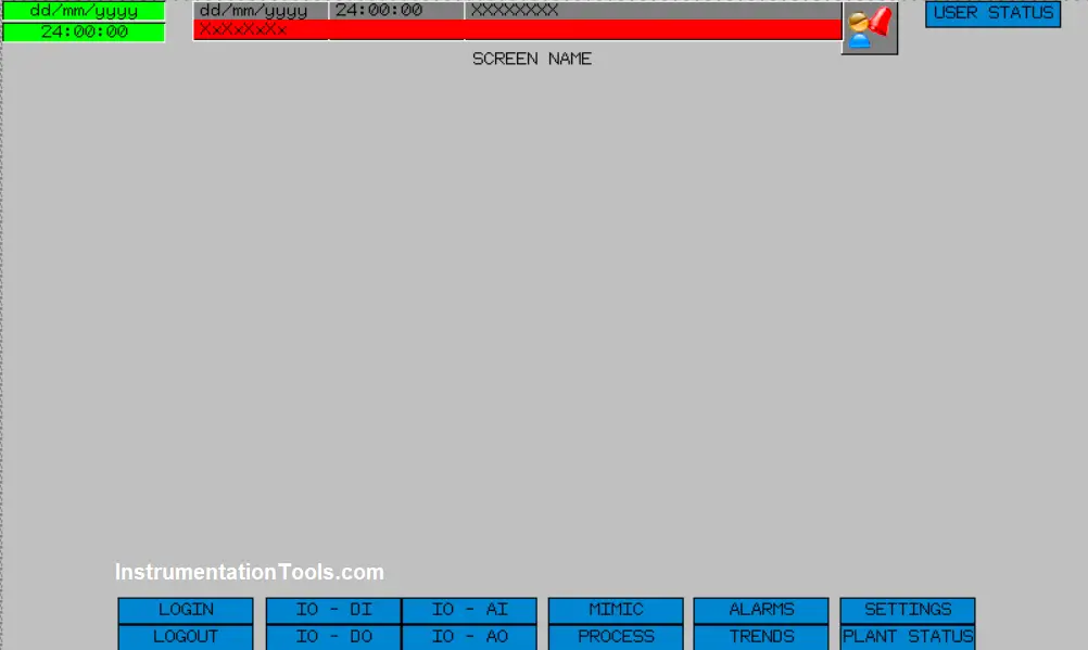
Also, apart from this, an alarm banner is shown in the header. You must be thinking that when we are already giving a button to view the alarm status screen, why this separate banner?

Well, in any critical system, if any alarm occurs, then it would be helpful if the user gets to see the alarm immediately without even touching anything. This saves time in troubleshooting. So, it is important to map all the critical buttons which will be used in the whole HMI program, in the header and footer.

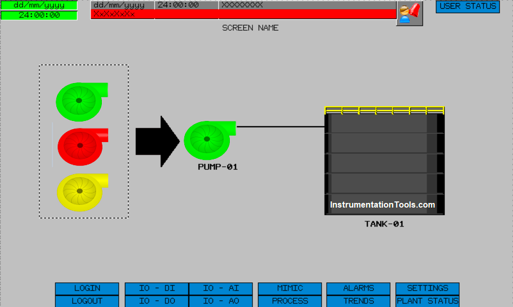
The next step in designing is to give standard colors to the equipment used for indicating its off-state, on-state, and trip-state. Most of the users denote red color even in trip conditions. It would be very helpful if we indicate yellow color for trip indication. This will help the user in distinguishing between off-state and trip-state; prompting immediate action.

Otherwise, the operator will have to check the alarm screen every time to find out why a device is not working; because in both the cases of off and trip, the equipment is off and not running.

Refer to the below image for understanding, where a pump has been used and it will be animated by three color states for the corresponding stage. Easy color identification from a distance helps the user to monitor the plant more efficiently.

PLC HMI systems for hazardous areas

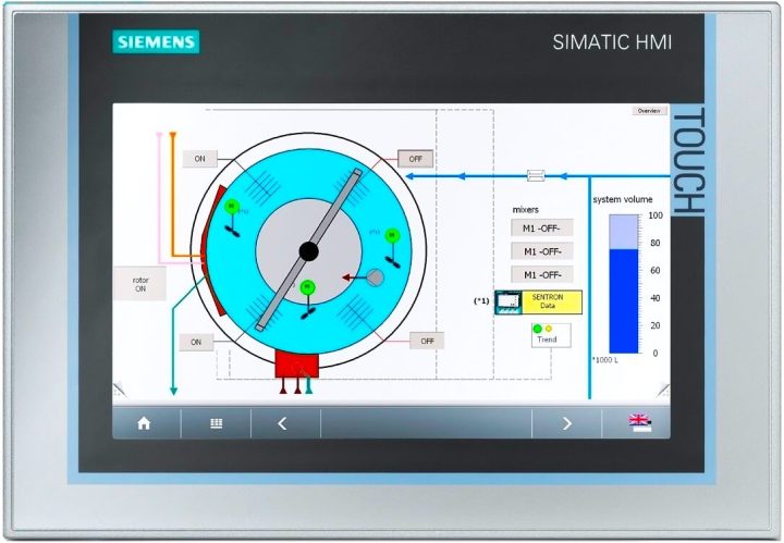
Next thing comes a faceplate. When the user finds any alarm or if he wants to just generally the status of equipment, a faceplate should be created, as shown in the figure.

A faceplate is a common box that opens when someone clicks equipment. This enables them to see or operate that equipment on that page only, rather than moving here and there. This makes troubleshooting easier and more efficient.

Also, in case of an alarm in the equipment, try to highlight a symbol near it. The symbol, like shown as a yellow triangle in the image, depicts some sign to be attended by the user for that corresponding equipment.

HMI Screen Design for Hazardous Applications

From this whole design, you can see how a user can easily navigate and operate the system with a single screen. If there are multiple HMI screens designed in a system and if the user has to navigate every time a lot, then for such hazardous and critical applications, the operator will take a lot of time to troubleshoot.

If you liked this article, then please subscribe to our YouTube Channel for Instrumentation, Electrical, PLC, and SCADA video tutorials.

You can also follow us on Facebook and Twitter to receive daily updates.

Read Next:

  • Types of Tags in SCADA
  • SCADA and HMI Systems
  • Delta HMI and VFD Logic
  • PLC Best Practices and Tips
  • What is Contextual HMI?
Don't Miss Our Updates
Be the first to get exclusive content straight to your email.
We promise not to spam you. You can unsubscribe at any time.
Invalid email address
You've successfully subscribed !

Continue Reading

How to Create DFB in Schneider PLC? – Derived Function Block
Turbine-Compressor System Architecture
Top PLC Manufacturers
What is Sequential Function Chart (SFC?)
Motion Detection based Street Light: PLC Logic Solution
Finding the Best PLC for Your Project – Tips and Tricks
Share This Article
Facebook Whatsapp Whatsapp LinkedIn Copy Link
Share
Leave a Comment

Leave a Reply Cancel reply

Your email address will not be published. Required fields are marked *

Stay Connected

128.3kFollowersLike
69.1kFollowersFollow
210kSubscribersSubscribe
38kFollowersFollow

Categories

Explore More

Pulse Timer Instruction in PLC Programming
Boolean Logic to PLC Programming
How to Operate a Group of Induction Motors using PLC Logic?
Programmable Logic Controller (PLC) Scan Time – Types, Theory
Machine Indicator Lights: PLC Programming Solution
ON Delay Timer using PLC
Components of PLC
Rockwell Automation Allen Bradley PLC for Smaller and Medium Projects

Keep Learning

Yokogawa DCS CPU

System Cabinet Health Checks – PLC and DCS Industrial Automation

Simatic 300 Station Configuration

Monitor and Modify Variables in Simatic Manager

Program to implement T Flip Flop logic

T Flip Flop PLC Ladder Diagram

PLC Counter Example for Bank

PLC Program for Bank Counter Application

Set the S5 timer value by a memory word

Set the S5 Timer Value by a Memory Word

Code Simulation of Safety Circuit

Feedback Monitoring in Safety PLC

Forward reverse motor control diagram with timer

Timer during Motor Direction Change PLC Program

PLC Instruction List Code

PLC Instruction List Program for Basic Instructions

Learn More

Pressure Reducing and Desuperheating Station (PRDS)

Pressure Reducing and DeSuperheating Station (PRDS)

Purpose of Emergency Shutdown (ESD) System

Purpose of Emergency Shutdown (ESD) System

0-10 VDC to 0-20 mA Conversion

How to Convert Voltage to Current using Resistor ?

Instrument Switch Status

Define Normal Status of a Process Switch ?

Elevator Control

Elevator Control: PLC Program with 5-Second Floor Stops

Chromatography Questions & Answers

Liquid Chromatography Questions & Answers

Power Electronics Objective Questions

Thyristor Chopper Circuits Objective Questions

PLC based Drink Dispenser System

PLC based Drink Dispenser System

Menu

  • About
  • Privacy Policy
  • Copyright

Quick Links

  • Learn PLC
  • Helping Hand
  • Part Time Job

YouTube Subscribe

Follow US
All rights reserved. Reproduction in whole or in part without written permission is prohibited.
Welcome Back!

Sign in to your account

Username or Email Address
Password

Lost your password?