H & B Gas Analyzer Principle and Calibration Procedure
Objective:
H& B make gas analyzer (For Measuring CH4, CO2, and Co) Principle & Calibration Procedure.
Principle:
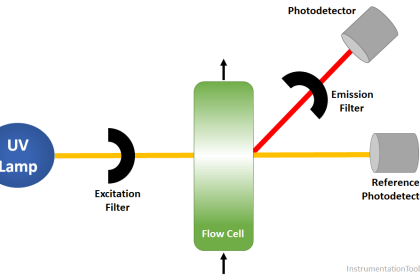
Gas analyzers works on NDIR (Non dispersive Infrared sensor)
The main components of NDIR sensors are an infrared source, a sample chamber and an infrared detector. The IR light is passed through the sample cell & Reference cell and reaches the detector. Reference cell is filled with a gas, typically nitrogen.
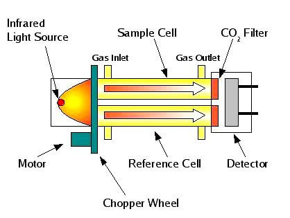
The gas to be measured is called as sample gas. This sample gas passes through the sample cell. A chopper is used to split the source i.e. IR rays to pass via both sample and reference cells.
The gas in the sample cell causes absorption of specific wavelengths according to the Beer–Lambert law, and the attenuation of these wavelengths is measured by the detector to determine the gas concentration. The detector has an optical filter in front of it that eliminates all light except the wavelength that the selected gas molecules can absorb.
Also See : NDIR Gas Analyzer Animation
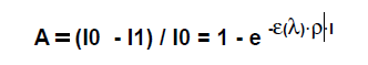
The relationship between measured infrared radiation absorption and the measurement component is based on the LAMBERT-BEER law:
Where
A = Absorption
I0 = Radiation entering the cell
I1 = Radiation leaving the cell
ε(λ) = Sample component extinction factor
ρ = Sample component density
l = Sample cell length
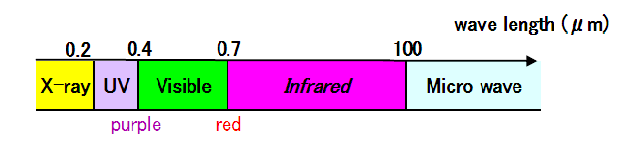
Infrared rays: Infrared rays is a part of electromagnetic wave of which wavelength is longer than visible red.
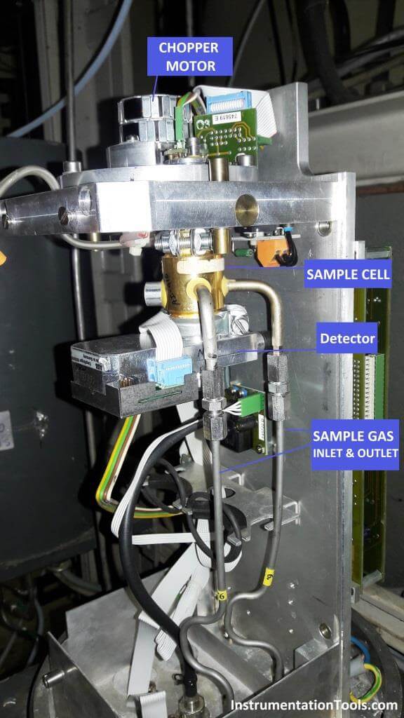
Parts of Gas analyzers:
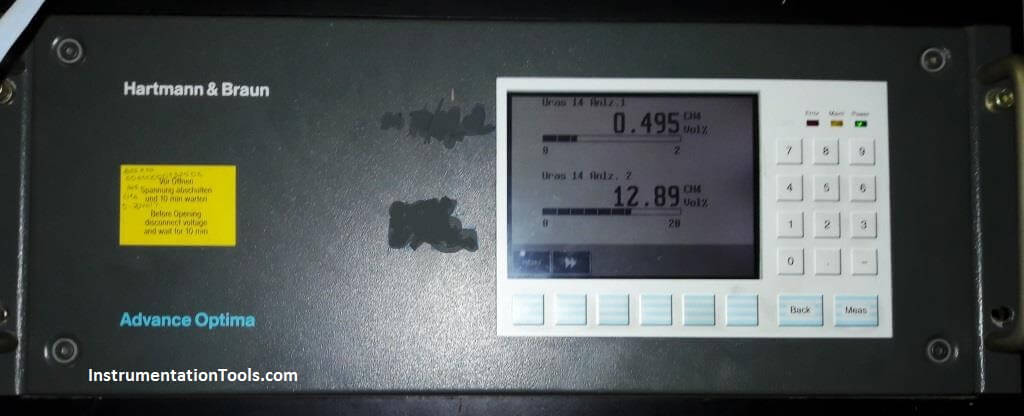
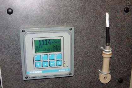
Display Unit: Display unit shows the concentration of gas values and for user interface.
IR radiation: Generated by broad-band emitter
Sample Cell: In sample cell there are two chambers 1. Reference chamber 2. Sample gas chamber. Reference chamber is filled with Inert gas like as N2 gas. Cell length differs according to the measurement range. The IR radiations will be spitted by chopper motor and passes through both sample and reference chambers and reaches the detector.
Gas Detector: The detector measures the intensity of IR rays which are received after passing via sample and reference cells. The IR rays intensity is measured and converts into equivalent gas concentration readings.
The preamplifier has 3 jumpers to allow signal matching to x1, x3 or x10. These jumpers are set during the initial calibration
Chopper Motor: Instead of using two individual sources or IR rays transmitters, we can use single source with a Chopper motor. The chopper splits the IR rays from the source to pass through the reference and sample cells. So that the infrared light from the source/emitters passes alternately through each cell twice per revolution.
Configuration of analyzers:
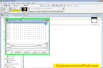
For configuration of H&B URAS 14 : install the TCT software and communicate with analyzer then open its software application, following page opened
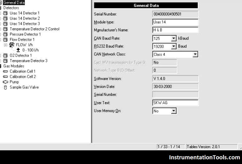
- Add the URAS 14 detector 1 and select the gas which you want to measure and which detector is installed. Then enter the gas concentration range.
- Add a pressure detector and enter the range ( say 0-100 kpa )
- Add a temperature detector and enter range (say 0 – 100 degc )
After this send the data to sample cell unit.
Calibration Procedure:
Make: H&B, Model: Uras 14
For calibration, go to calibration mode by display menu then enter into manual calibration menu.
- Isolate the sample gas and open the valve of zero gas (N2 gas) , then select zero calibration menu then enter the concentration of zero gas value, press enter and wait for sometime to stable the readings, after stabilizing the reading press enter for zero calibration.
- For span gas calibration open the valve of span gas, then select span gas calibration menu then enter the value of span gas cylinder concentration value and wait for sometime to stable the readings, after stabilizing the reading press enter for Span calibration
After this go to measuring display menu.
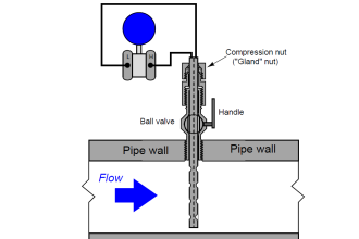
Sampling System :
For any gas analysis, to obtain respective sample of the stream is very important. The sampling system equipment’s should be able to continuously purify and deliver the gas sample to the gas analyzer.
If sample gas has dust, condensate and corrosive substances then these may disturb the analyzer performance and its analysis, therefore sampling system should include dust filters, measuring gas cooler, absorption filter, mist filters and condensate separators etc.
The sample gas flow and the bypass flow must be connected to the atmosphere or to an unpressurized exhaust gas collecting system at an adequate distance from the Gas analyzer.
Routine Activity for Gas analyzers :
- Sample condensate flushing /drain moisture catch pot from its primary sampling system as well secondary sampling system
- Sample pressure to be noted and maintained at required value
- Ensure proper Sample flow, Pressure & temperature values
- Monitor electronics/Check for any alarm messages and take care timely action.
- Timely Calibrate the gas analyzers as PM schedule.


Plz ABB GAS ANALYSER DETAILS
Hi.
Do you know where I can train to calibrate gas flue analysers in the UK?
Many thanks, Steve