Basic Guidelines to be followed during Logic Checks
(Follow Cause & Effect, Control Narrative, P&ID and Latest Alarm & Trip Schedule):
1. Understand the Cause & Effect Matrix, if any changes/modification required, make a note.
2. Compare the cause & effect matrix with graphic & note for any changes to be done like resets, tag no, effects etc. (The C&E matrix may be old versions on the graphics. So this check is necessary with latest available C&E).
3. List the Cause Tag & Effect Tags and Get clearance from respective In-charge Persons before starting Logic Checks.
4. If Rotary equipments are involved, it should be started actually in Field or should be taken in Test Mode (Mention in Punch point that it was checked in TEST Mode). When clearance is obtained, one or 2 logics should be checked by taking Pump in running mode actually.
5. Keep one Operation Person in Field while logic checking
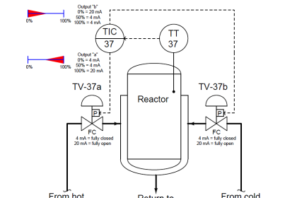
6. If SDV’s or Control Valves has to close while creating a cause, keep them open before creating a Cause or Vice-versa. When control valves goes to close condition during logic checking, check whether it is operating or not. It should not operate till cause exits.
7. The values for the Causes to be simulated – Refer Latest Alarm & Trip Schedule
8. Check for Causes & Effects alarms in Alarm Window and changes in DCS Graphics & ESD C&E Graphics
9. Check for effects actually in Field only and confirm with the logic.
10. For SDV’s – SOV Command and Open / Close alarm / Control Room Reset / Field Reset should come.
11. For Motors – Check for Trip alarm in Faceplate, Alarm Window & blinking on graphic display.
12. Keep one copy of Cause & Effect Matrix & highlight what are really actuated in Field. If only trip alarm or ESD signal checked, don’t highlight it, write punch point
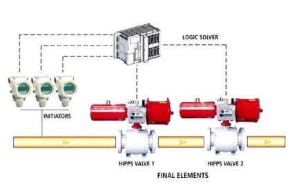
13. For 2 out of 3 logic, 3 combinations should be checked (AB/BC/CA). For one combination, check for actual effect in Field and for others check for signal in Engineering station. If it is very important like HIPPS – Check for all combinations. (Check for high difference between all three transmitters for different readings & check the effects.
14. If there is no clearance for motors – Check for ESD signal & alarms in Face plate & Alarm window. (Don’t Highlight in C&E matrix and mention in Punch point that to be again checked when Motor is ready)
15. If any deviations like – Mismatch, effects not happening actually in Field, no alarm appeared etc., Mention in C&E sign-off page and in DPR.
16. Once cause is activated, while normalizing carefully check for Hysteresis & Resets which are mentioned in C&E diagram.
17. After verifying logics, check for Maintenance Override & Start-up Override also.
18. Whatever effects not checked, clearly mention in C&E sign-off page that it has to be checked again.
19. While Checking Control Narrative, refer updated document. Check for actual action as per our Process conditions.
For Ex: If control valve has to open to maintain process set point, it should open or vice-versa. If any deviation from Control Narrative – (Direct / Reverse Acting) implement changes.
20. While checking the control narrative for control valves, always keep Set point constant & vary Measured Variable and check for the output from the controller & check whether the action is correct or not according to your process requirement.
If Process value is increasing more than Set point, control valve opening has to rise for Direct Acting & Control Valve opening has to reduce for Reverse Acting & vice-versa. Also confirm from face plate & field & note the observations.
21. For Fire & Gas Logic Checks, the simulation to be done from Field & Effects to be checked in Field. (For Ex: If it is 2 out 8, randomly simulate 2 different type of causes. and observe the Hooter response)
22. One O&M Person should be there in Field, to verify that the activation of Detectors/Manual Call Points are forced in that Particular area or not & tag number and location to be verified as per Layout Drawings.
23. Check for Causes & Effects alarms in Alarm Window and check for changes in FGS Graphics & FGS Cause & Effect Matrix.
24. Confirm in Field, the Gas Beacon (Amber color), Gas Hooter activates for Gas Detection only.
25. In the same way, confirm Fire Beacon (Red color) / Hooter activates for Fire Detection & Manual Call Points activation only.
26. Both Hooter sound should be different.
27. Highlight in C&E page, which are actually happened in Field only. If only signal checked, don’t highlight, write Punch point.
28. Finally mark-up in Master Copy Cause & Effect.
Also Share any other points if we missed from the above list via comments.
Also Read: Transmitter Calibration Procedure


I was liked your pages 3 months ago, it is so much useful for me. Sir I am an instrument engineer in coal fired thermal power plant. I want to learn about dcs logic. What I have to do for learning dcs logic
The information , which you have provided is very much use full. Right from expert engineer to to a beginner is very delighted to read your articles.
very useful guidelines
very useful. thanks so much.
if you have any demonstration by real example/video. that would be best.
Please post commissioning procedure also…with an example
Various instructions given by you give confidence to technicians