Different Blocks structures are available when programming a PLC, these blocks include Functions FCs, function blocks FBs, and data blocks DBs. These blocks are very handy tools that you can use to better design your PLC logic and make your code more readable and easy to follow and debug
In previous articles, we discussed the FCs and FBs. In this article, we will discuss the Data Block DBs, more specifically the Global Data Block.
Contents:
A data block DB is a memory area that is used to save the values of the parameters that are written during the execution of the PLC program.
Opposite to the code block, the data block DB contains only variable declarations. It doesn’t have any networks or instructions like an FC or an FB has. The structure of the DB is defined by how many variables you have declared inside the data block.
There are two types of data blocks:
As the name suggests, the global data block is globally declared for the whole PLC logic. It is not assigned to a specific code block. You can access the values of a global data block from any code block anywhere in your PLC logic. A global data block contains only static tags.
The structure of the global data block can be freely defined. In the declaration table for data blocks, you declare the data elements that are to be contained in the global data block.
The instance data block is assigned directly to a function block FB, whether this function block is internally defined in the PLC like Timers and Counters or user-defined Function blocks FBs.
The structure of an instance data block cannot be freely defined but is instead determined by the interface of the function block. The instance data block contains exactly those block parameters and tags that are declared in the Function block interface.
However, you can define instance-specific values in the instance data block; for example, start values for the declared tags.
Available only for S7-1500 CPUs, ARRAY data blocks are global data blocks that consist of an ARRAY. This ARRAY can be based on any data type.
For example, an ARRAY of a PLC data type (UDT) is possible. The DB contains no other elements besides the ARRAY. Because of their flat structure, ARRAY data blocks facilitate access to the ARRAY elements and their transfer to called blocks.
The “Move operations” section of the “Instructions” task card offers options for addressing ARRAY DBs.
In this article, we will take about the global data block, and we will discuss the other two types in separate articles.
Data blocks are used to store PLC program data. That means they contain variable data that is used by the user program. Global data blocks store data that can be used by all other blocks.
The maximum size of data blocks varies depending on the CPU. You can define the structure of global data blocks any way you, please.
You also have the option of using PLC data types (UDT) as a template for creating global data blocks.
Every function block FB, function FC, or organization block OB can read the data from a global data block or can itself write data to a global data block. This data remains in the data block even after the data block is exited. See picture 1.
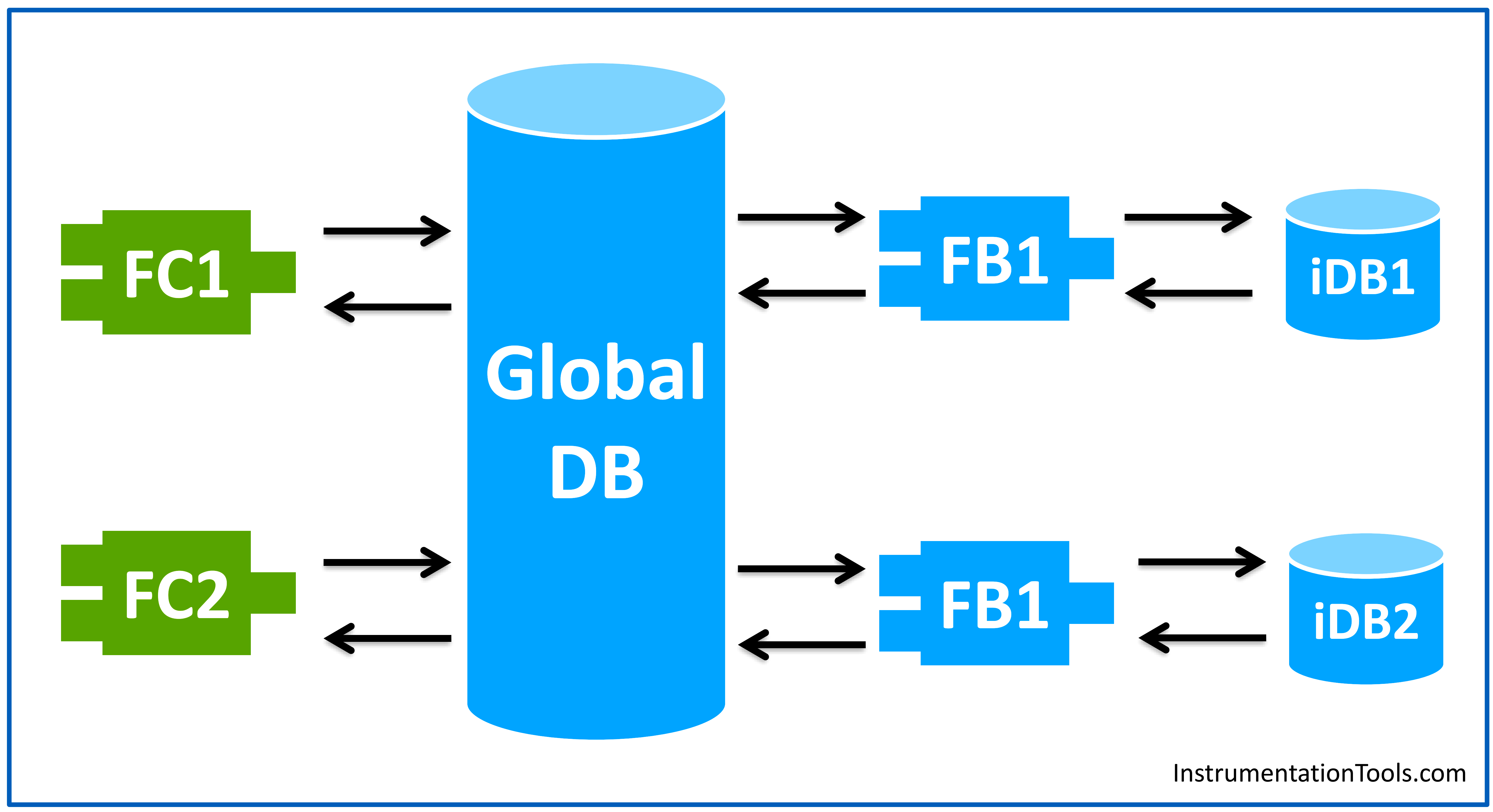
As you can see from the previous picture, a global data block can be accessed from any code block inside the PLC program, whereas the instance data block can only be accessed by the associated function block.
You create a global data block the same way you create a function FC or a function block FB. From the add a new block to your project tree. See picture 2.
Let’s declare some variables inside the Global data block.
You do that by clicking the add new under name section writing the variable name that you want and then choosing the variable data type. See picture 3.
We already showed how to declare a tag/variable in picture 3.
The start value of a tag is a value defined by you, which the tag assumes after a CPU startup. The value must match the data type of the tag and should not exceed the range of the data type. See picture 4.
The tag takes the defined value at startup, provided it was not declared as retentive.
So, if I set the Tank1Level start value to any value other than zero, this value will be applied the next time the PLC is restarted. See picture 5.
To prevent data loss in the event of power failure, you can mark the data as retentive. This data is stored in a retentive memory area.
The options for setting the retain depend on the type of data block and the type of block access that is set. See picture 6.
As you see in picture 6, the Tank2Level variable is set to be a retained value, which means even if the PLC stopped or there was a power failure, the Tank2Level will have the same data stored when the PLC is on again. It will not be reset to the start value.
In a global data block, you can define if a variable can be visible from the HMI tag tables or not. You can also define if this variable can be read or written from the HMI. See picture 7.
The default setting for any declared variable in a global data block is that it can be accessed, read, and writable from HMI. If you want to disable this feature for a certain variable, you have to uncheck the accessibility option for that variable.
So far we created a global data block and declared some variables inside.
Now we will try to run a simulation of the program and see if we can better understand what a global data block is.
Two PLC simulations are provided below.
Check the following animation explaining the start value of a variable inside a global data block.
Animation 1 Explanation:
Check the following animation explaining the retain option of a variable inside a global data block.
Animation 2 Explanation:
Downloads:
A global data block can be accessed from anywhere and by any block that exists in the PLC program. You can declare as many variables as you want inside a global database.
The best practice technique is to create separate data blocks for the different sections of your logic, to make it very easy to follow your logic. For example a separate data block for all the variables that need to be read or written by an HMI.
If you liked this article, then please subscribe to our YouTube Channel for PLC and SCADA video tutorials.
You can also follow us on Facebook and Twitter to receive daily updates.
Read Next:
Learn an example PLC program to control a pump based on level sensors using ladder…
In the PLC timer application for security camera recording, when motion is detected then camera…
In this example, we will learn batch mixing with PLC ladder logic program using timer…
This PLC example on manufacturing line assembly is an intermediate-level PLC program prepared for the…
In this article, you will learn the PLC programming example with pushbutton and motor control…
This article teaches how to convert Boolean logic to PLC programming ladder logic with the…


