Automated garage gate control system to open or close the gate whenever car arrives or leaves using sensors and PLC ladder logic.
Note: Please acknowledge that this program is for educational resource for comprehending ladder logic with accessible applications.
Automated Garage Gate Control
Problem Statement:
Design a PLC ladder logic for the following application.
We are using one Sensor & “Parking Paid” status to control the Garage Gate.
When a Car arrives then open the gate for 10 seconds. If the car leaves within 1 minute, then the gate opens automatically.
After 1 minute, the gate will be opened when the status is “parking paid”.
Automation Training Videos
Instrumentation Tools provides you the best automation training videos for you.
This video explains the garage gate application for car parking.
Inputs and Outputs
Digital Inputs:
Sensor: I0.0
Parking Paid: I0.1
Digital Outputs:
Garage Gate: Q0.0
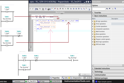
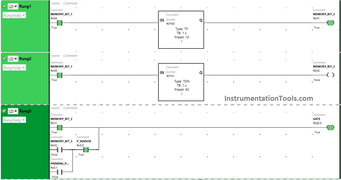
PLC Ladder Logic
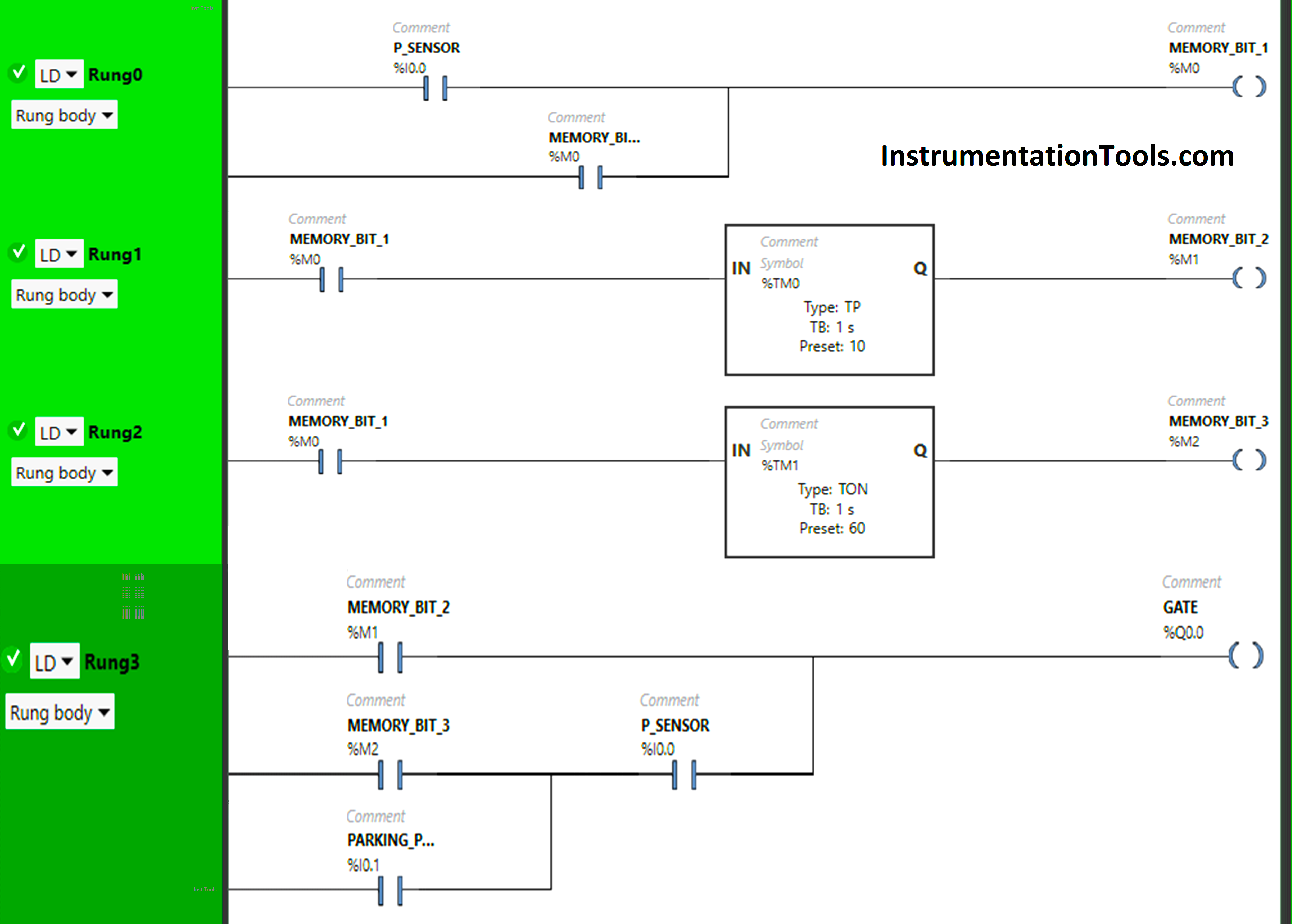
Logic Explained
We have used Normally Open Contacts for P-Sensor(I0.0), Parking Paid (I0.1) and Memory Bits.
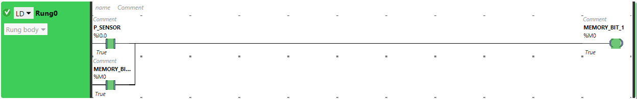
In Rung 0:
- Normally Open Contact is used for P-Sensor (I0.0) to Turn ON Memory Bit 1 (M0).
- Memory Bit 1 (M0) is latched so that when P-sensor (I0.0) turns OFF, Memory Bit 1 (M0) still remains ON.
In Rung 1:
- Normally Open Contact is used for Memory Bit 1 (M0) to Turn ON Memory Bit 2 (M1).
- Timer-type TP is used to Turn ON Memory Bit 2 (M1) for a limited time.
In Rung 2:
- Normally Open Contact is used for Memory Bit 1 (M0) to Turn ON Memory Bit 3(M2).
- Timer-type TON is used to delay the turning ON time of Memory Bit 3(M2) for some time.
In Rung 3:
- Normally Open Contact is used for Memory Bit 2 (M1), Memory Bit 3 (M2), P-Sensor (I0.0), and Parking Paid (I0.1) to Turn ON the output Garage Gate (Q0.0).
- Memory Bit 2 (M1), Memory Bit 3 (M2) + P-Sensor (I0.0), and Parking Paid (I0.1) are connected in parallel, thus implementing OR Logic Gate.
- Memory Bit 3 (M2) and P-Sensor (I0.0) are connected in series, thus implementing AND Logic Gate.
Simulation Results
We will see the results of the PLC program simulation. We may show the partial logic code instead of all rungs in the below test cases.
When P-Sensor detects a car or When a car arrives
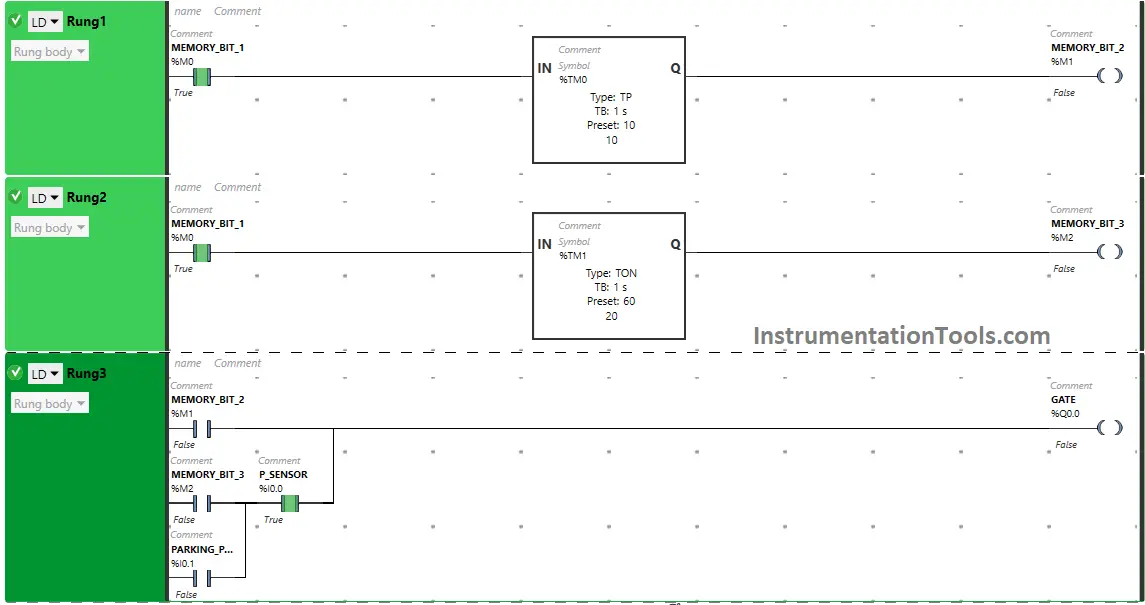
When P-Sensor (I0.0) detects a car ( when a car arrives), Memory Bit 1 (M0) turns ON and stores the data that car has arrived as Memory bits stores the data. Memory Bit 1 (M0) is latched so that when the P-sensor (I0.0) turns OFF, Memory Bit 1 (M0) still remains ON.
When Memory Bit 1 (M0) turns ON in Rung0, Normally Open Contact used for Memory Bit 1 (M0) in Rung1 will be in True State and will pass the signal to turn ON Memory Bit 2 (M1) but only for 10 seconds as Timer Function Block type TP is used to turn ON the Memory Bit 2 (M1) for Limited time. The time is set to 10 seconds.
After 10 seconds, Memory Bit 2 (M1) will turn OFF. When Memory Bit 2 ( M1) turns ON in Rung1, Normally Open Contact used for Memory Bit 2 (M1) in Rung3 used to turn ON the output Garage Gate (Q0.0) will be in True State and will pass the signal to turn ON the output Garage Gate (Q0.0) (Gate Opens).
In Rung1, when Timer Function Block type TP reaches its set time i.e 10 s, Memory Bit 2 (M1) will turn OFF in both Rung1 and Rung3, and when Memory Bit 2 (M1) turns OFF in Rung3, the output Garage Gate (Q0.0) turns OFF (Gate Closes).
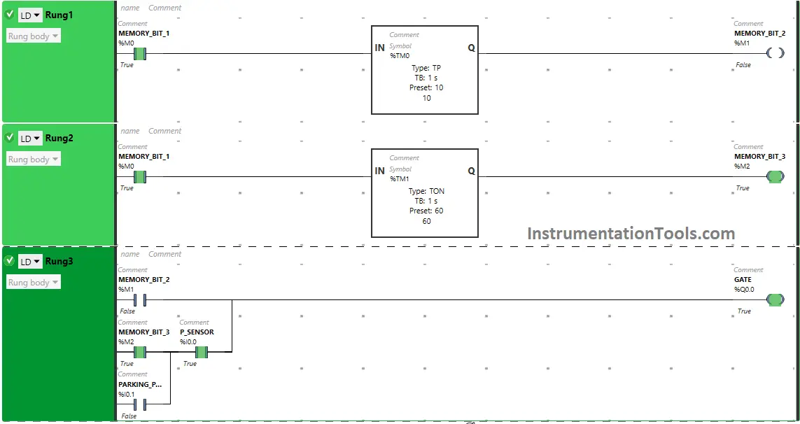
If the car leaves within 1 minute and P-Sensor detects a car again
When Memory Bit 1 (M0) turns ON in Rung0, Normally Open Contact used for Memory Bit 1 (M0) in Rung2 will be in True State and will pass the signal to turn ON Memory Bit 3 (M2) after 60 seconds as Timer Function Block type TON is used to delay the turning ON time of the Memory Bit 3 (M2). The time is set to 60 seconds.
So after 60 seconds, Memory Bit 3 (M2) turns ON. When Memory Bit 3 ( M2) turns ON in Rung2 or ( Car leaves within 1 minute), Normally Open Contact used for Memory Bit 3 (M2) in Rung3 used to turn ON the output Garage Gate (Q0.0) will be in True State and P-sensor (I0.0) detects a car, the output Garage Gate (Q0.0) will turn ON (Q0.0) (Gate Opens).
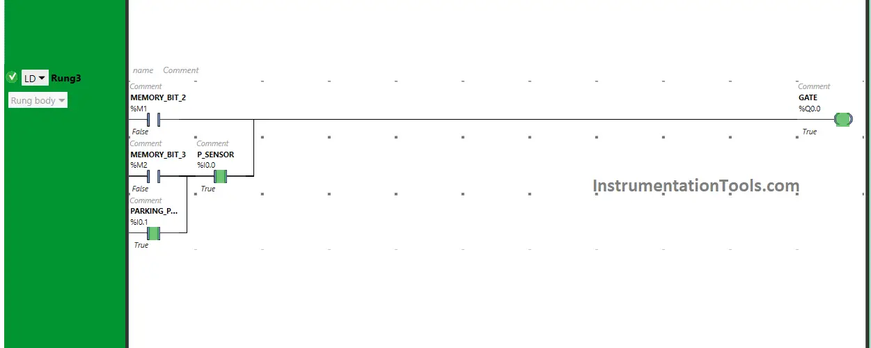
When the status is Parking Paid
When Parking Paid (I0.1) is turned ON or (when status parking paid) and P-Sensor is turned ON ( P-Sensor detects a car), the output Garage Gate (Q0.0) will turn ON or ( Gate opens).
If you liked this article, please subscribe to our YouTube Channel for PLC and SCADA video tutorials.
You can also follow us on Facebook and Twitter to receive daily updates.
Read Next:
- Up Down Counter Instruction in PLC Logic
- Cars Garage Counter From the Same Door
- PLC Logic Auto Sugar Bag Filling Station
- SCADA Level Control System Software
- PLC Programming Two-Hand Control