Valves, the actuators that move them, and the electronic circuits that control them, are all subject to aging soon after they are installed. Valve seats wear from repeated seatings and from the liquid or gas that passes through them.
A valve may be stroked up to tens of thousands of times a year, which causes screws to reposition, springs to weaken and mechanical linkage to loosen. Electronic components change value over time.
All of that can produce valves that don’t fully open or close, close prematurely, or operate erratically. This “calibration drift” can result in improper regulation of the gas or liquid under the valve’s control.
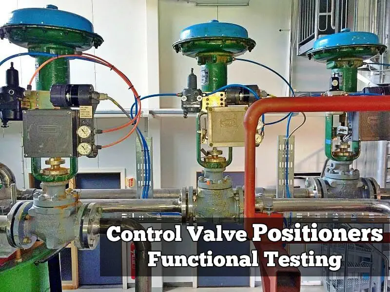
Functional Testing of Control Valve Positioners
To keep valves operating properly, you need to periodically check electronic valve positioners. However, these checks need to be conducted quickly to minimize down time. If calibration drift is found, the valve positioner must also be recalibrated immediately.
A good tool for this is source meter or a handheld field tester like the Fluke 789 ProcessMeter that can be used to test and re-calibrate electronic valve positioners. It offers signal sourcing to simulate a controller connected to a valve positioner’s input and can continuously adjust the source current in incremental steps, so you can check the valve’s linearity and response time.
Here are the basic steps for checking a normally closed valve :
- Set up the SourceMeter in sourcing mode using the appropriate range of current for the positioner.
- Insert the source current test leads into the mA output jacks.
- Select the 4-20 mA range by moving the function switch from Off to the first mA output position.
- Connect the meter mA output to the input terminals of the valve positioner.
- To determine if the positioner is fully closes the valve at 4 mA, adjust the source current to 4.0 mA using the push button. The valve should be closed.
- While watching the valve for any movement, press the Coarse Down button once to decrease the current to 3.9 mA. There should be no movement of the valve.
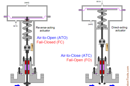
- In setting the point at which the valve starts to open, make sure there is no counter pressure by the actuator against the force holding the valve closed when there is 4.0 mA on the controller’s input. In a spring-to-close valve, there should be no pressure on the diaphragm. With a double acting piston actuator, there should be no pressure on one side of the piston. To ensure that there is no counter pressure at the closed setting, you may want to set the start of opening between 4.1 and 4.2 mA.
- To check the opening of the valve, press the Coarse Range Up button from 4.0 mA. Each press of the Coarse Range Up button will increase the current 0.1 mA. You should adjust the zero adjustment on the positioner to set the valve for the closing characteristic desired.
- To check the valve at the fully open position—called a span position check—adjust the source current to 20 mA using the range buttons and allow the valve to stabilize. While watching or feeling for valve movement, press the Coarse Range Up button once to 20.1 mA. The valve movement should be as small as possible and can be adjusted using the span adjustment on the positioner.
- Using the coarse control, adjust current up and down between 20.1 mA and 19.9 mA. There should be no movement of the valve stem from 20.1 to 20 mA and slight movement from 20 mA and 19.9 mA.
- In most valves, there is an interaction between the zero and span settings of a valve controller, so it is best to ensure proper valve position adjustment by repeating the test of the fully closed and fully open positions until no further adjustment is necessary.
- For valves with linear action, linearity can be checked by setting the SourceMeter to 4 mA and using the % Step button to step the current to 12 mA (50%) and confirm the valve position indicator is at 50% travel. If your valve is a non-linear type, refer to the valve manual for proper operation.
- To check for smooth valve operation, turn the rotary switch to output mA and select Slow Linear Ramp. Let the meter ramp the mA signal through several cycles while you watch or feel for any abnormal operation of the valve. The valve should NOT oscillate or hunt at any of the step positions of the Slow Ramp. The valve also should not be sluggish. Set the gain of the valve controller to a point that gives the best response between these two conditions.
Safety notes:
- Manufacturer’s specific instructions should always be consulted for proper and appropriate valve positioner testing and calibration.
- Always ensure that the personnel responsible for the process you are working on are informed of your intentions prior to making any checks of valve operation. Be alert when touching any moving machinery.
Source : Fluke


Thanks For Sharing Information.
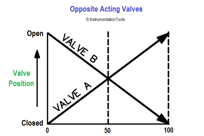
Good sharing.keep it up. By the way can you share on functional test and stem travel for nonlinear valves eg. Quick opening and equal percentage. Thanks again.
Thanks for sharing very useful
thanks for the information
THANK YOU FOR THE ARTICLE.
DO YOU HAVE AN ARTICLE ABOUT THE FISCHER DVC 6000 POSITIONER?
THANKS.
thanks for everything…
how you trouble shoot if they say that the level is not controlling that the control,valve movement is eratic