Flow Measurement Questions: Preparing for Field Instrumentation Interview then read this article about flow measurement and test yourself.
Flow Measurement Questions
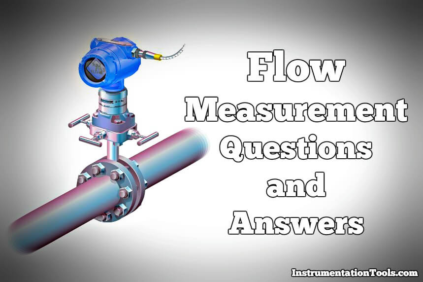
Why was RTD installed after the Orifice Flow element?
The location of RTD (thermowell), is positioned downstream of the orifice plate so the turbulence it generates will not create additional turbulence at the orifice plate.
The American Gas Association (AGA) allows for upstream placement of the thermowell, but only if located at least three feet upstream of a flow conditioner.
A major reason for this is von K´arm´an vortex shedding caused by the gas having to flow around the width of the thermowell. The “street” of vortices shed by the thermowell will cause serious pressure fluctuations at the orifice plate unless mitigated by a flow conditioner, or by locating the thermowell downstream so that the vortices do not reach the orifice.
What is the difference between mass flow and volumetric flow?
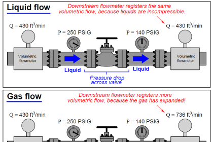
Mass flow is the movement of a fluid over time quantified relative to the fluid’s mass. Volumetric flow is the movement of a fluid over time quantified relative to the fluid’s volume.
From a practical standpoint, volumetric flow will vary with changes in temperature and pressure, while mass flow is unaffected by these changes.
Volumetric Flow Rates vs Mass Flow Rates
At standard conditions (1 atm, 25°C), volumetric and mass flow rates are nearly identical. However, rates differ dramatically with temperature and pressure changes.
For example, if volumetric flow was used to fill balloons with 250 mL of helium, but the incoming line ran near a cycling furnace—intermittently heating the incoming helium—the balloons would initially be the same size, but would then be different sizes once they reached an equilibrium temperature.
If a mass flow reading was used, the balloons would initially be different sizes but would be the same size upon reaching an equilibrium temperature.
For applications at standard temperature and with no back pressure on the meter outlet, select a volumetric meter. For fluctuating pressures and/or temperatures, select a compensated mass meter.
Also Read : Comparison of Venturi and Orifice flow meter
How is the unit of standard cubic centimeters per minute (sccm), which sounds like a volumetric unit, actually a mass flow unit?
The sccm unit is a little confusing. It is typically used in meters to allow users to easily derive a corresponding traditional mass flow unit from a measurement that is not native to the meter’s sensing technology.
These meters will typically use a native volumetric flow sensor to measure a flow quantity. Then they compensate or “standardize” that measurement to a specific reference condition often referred to as standard temperature and pressure (STP).
This standardized flow rate allows a user to easily reference a density for their known gas composition and use it to calculate an equivalent mass flow in the units of their choosing.
It’s important to understand that this mass flow must be derived since it isn’t physically measured by a mass flow sensor.
What is flow meter compensation?
Flow compensation is the act of determining the degree to which a particular volumetric flow rate would change if the temperature and/or pressure were to change.
What is the Principle of operation of Electromagnetic Flow Meters?
The working of these meters is based on Faraday’s Second Law of Electromagnetic Induction. It states that a conductor moving in a magnetic field with the direction of its motion perpendicular to the magnetic field generates an EMF across it and the direction of the EMF is perpendicular to both, the magnetic field and the direction of motion.
The generated EMF is proportional to the magnetic flux density, B, the velocity of conductor v, and the length of the conductor l. In the flow meter the magnetic field is generated by exciting the coils and the conductor is the liquid itself, under measurement with a length equal to the diameter of the pipe.
Thus EMF = B.v.d,
where d is the diameter of the inner wall of the flow meter.
What is the level of conductivity required for the liquid under measurement to get satisfactory operation of the meter?
In general, the electrical conductivity of liquid under measurement should have a minimum of 5 micro Siemens per cm. conductivity.
But carefully designed transmitters and primary flow sensors, like Manas, can measure the flow rate of liquids having conductivity as low as 1 micro Siemens per cm.
Can an Electromagnetic Flow meter be used for the measurement of the flow of liquids like Petrol, Diesel, Kerosene, Various types of oil, Edible oil, or other organic solvents?
As explained in question 2 above, the required conductivity of the liquid is at least 1 micro Siemens per cm. The conductivity of the liquids under question is nearing almost zero.
E.g. the conductivity of kerosene is in Pico Siemens, where even carefully designed meters also cannot measure the liquid flow.
Can the Electromagnetic flow meter measure the flow of fluids like steam, air, gases, or any such compressible fluid?
Electromagnetic flow meters are designed as Liquid Flow Meters.
They cannot measure the flow rates of compressible fluids.
Can an Electromagnetic Flow Meter be used for measurement of Mass Flow Rate?
If we refer to question no.1 above we find the basic equation as, E = B .v. d
Where E is the Electro-Motive Force generated in the liquid because of its average velocity. It is clear that for a given flow meter the magnetic flux density and diameter are constant.
The EMF is thus proportional to only the average velocity of the liquid. Velocity when multiplied by cross-sectional area gives us a volumetric flow rate.
The electromagnetic flow meters are thus volumetric flow meters and cannot be used as Mass Flow Meters.
If the density of the flowing liquid is fixed and if there is a facility to feed the density in the transmitter the E.M. Meter can be used as a Mass Flow Meter
What is the typical Accuracy of measurement for Electromagnetic Flow Meters?
The typical accuracy of these meters is +/- 0.3 % of reading.
The specified accuracy is +/- 0.5% of reading between 10 % to 100 % of the calibrated flow rate range.
What is meant by a full-bore meter?
A Full Bore meter is a circular meter where, when the flow passes by filling the entire bore area, the meter can measure the average velocity inside the meter.
Naturally, the accuracy of a full bore meter is always much better than any other type.
Also Read : Mass Flow Calculations
What is the difference between Insertion Type and Full Bore Type meter?
As explained in question 7 above the full Bore Meter measures the average velocity. The Insertion Type measures velocity at only one point.
So in fact Insertion Meters are velocity meters and not real flow meters. Naturally, the accuracy of the Insertion type, if used as a flow meter, is very poor.
What is the effect of change in velocity profile through the meter, on accuracy?
As long as the velocity profile is symmetrical around the axis there is no effect on accuracy with a change in velocity profile,
e.g. from laminar to turbulent or even transitional profile of velocity.
What is the minimum velocity for which the Electromagnetic Flow Meter works with consistent readings?
General purpose meter manufacturers do not recommend operating their meters below 0.2 to 0.3 meters/second velocity, but can comfortably be used for velocities as low as 0.1 meters/second.
What is the difference between a Wafer Style Meter and a Flanged type Meter?
Both types work on the principle of Faraday’s Law. Both are durable and accurate in measurements.
However, the lengths of flanged-type meters are specified by ISO standard, ISO13359, and those of wafer type are decided by the manufacturer.
Wafer-type meters do not have flanges and are installed by sandwiching the meter between two flanges of pipe.
There being no flanges to the meter, and the length being less the wafer meters are economical compared to flanged meters.
What is the difference between magnetic flow meters and magnetically coupled flow meters?
The measurement principle of magnetic or electromagnetic flow meters is based on Faraday’s Law of Electromagnetic Induction.
These meters contain no moving parts. As in magnetically coupled meters, measurement is not based on Faraday’s law but is based on the rotation of the wheel with a velocity of liquid. The rpm value of this rotating wheel is transferred to the outside measurement scheme by magnetic coupling.
Turbine-type and paddle-wheel-type meters usually use this scheme. These meters have moving parts and limitations on accuracy as well as durability and capacity to measure minimum velocity signals. Magnetically coupled meters are sometimes mistaken as magnetic or electromagnetic flow meters.
Can an Electromagnetic flow meter be used for the measurement of Boiler Feed Water?
The E.M. Flow Meter can be used for the measurement of Boiler Feedwater.
In this application, it is recommended to install the meter on the suction side of the feed pump.
What are the various names of Electro Magnetic Flow Meters?
These meters are known by various names like Magnetic Flow Meters, Magmeters, Fullbore electromag, Magnetic Inductive Flow meters etc.
How to commission the Magnetic flow meter at the site in an ideal case?
Two types of calibration :
- Wet Type &
- Dry Type
Wet calibrations that check the entire flow measurement system are generally not an option in most applications because challenging the installed flowmeter with a known volume of water is impractical — especially in large pipes in remote locations.
Even removing the flowmeter to perform a wet calibration in a flow laboratory can be expensive and time-consuming. Further, it does not take the installed piping into account.
On the other hand, dry calibrations verify the operation of only part of the flow measurement system. In the case of magnetic flowmeters, a traditional calibrator checks the transmitter by verifying that a given (millivolt) input produces the correct flow rate.
- What if the wiring is faulty?
- What if the coil has changed its characteristics?
- What if the flow tube leaked and shorted an electrode?
Dry calibrations do not necessarily check for these problems.
What is the principle of operation of Steam and other Gas Flow Meters?
There are various types of Flow Meters for Steam, Gas, and flow measurements.
The most popular type is based on the principle of creating a differential pressure across the differential pressure element like ORIFICE, VENTURY TUBE, etc.
The differential pressure thus created is related to the flow rate.
Qm α √(ΔP.ρ)
Where Qm is the Mass flow rate.
ΔP is Differential Pressure.
ρ is the Density of flowing Fluid.
Thus by measuring the differential pressure and density, one can compute the flow rate
Why Mass Flow Rate is measured? Why not Volume Flow Rate?
The volume of compressible fluid changes with changes in pressure and temperature. The mass remains constant irrespective of changes in the pressure and temperature of the fluid. It is therefore convenient to measure mass flow rate.
Volume flow rate also can be measured provided the reference conditions of temperature and pressure are well defined. The volume flow rate is then computed for these conditions thus avoiding the errors due to changes in pressure and temperature of fluid.
Steam flow meters display the reading in terms of mass, i.e. Tons/hour or Kg/hour etc. while Air or Gas flows measure flow in terms of Nm³ or Sm³ where N and S stand for reference conditions.
Also Read : Turbine Flow Meter Verification
What are the reference conditions for measuring volume flow rate?
There are two different reference conditions.
One is N.T.P. and the other is called S.T.P.
The normal condition of Temperature and Pressure is NTP.
The standard condition of Temperature and Pressure is STP.
The definitions for these conditions are defined but are interchanging in various countries. In India, they are defined as follows,
NTP: 0° C Temperature and 1 Atmosphere Pressure.
STP: 15° C Temperature and 1 Atmosphere Pressure.
Why does accuracy get hampered by variations in temperature and pressure?
As explained in question 2 above the volume of fluid changes with changes in temperature and pressure.
If we are measuring volumetric flow naturally we will find different readings of flow rate at different pressure and temperature for the same quantity of flow.
If we are measuring Mass flow rate, the density changes with a change in temperature and pressure.
so the flow rate readings will not be accurate (refer to the expression of mass flow rate in question 1 above.
How to avoid the effects of temperature and pressure variations while measuring the flow rate of compressible fluid? What is density compensation?
To avoid the effects of variation of temperature and pressure on flow measurement the flowing pressure and flowing temperature are measured.
From this data the density is computed and as per the expression given in question 1 above for mass flow rate the value for the same is calculated. Pressure Temperature compensation and Density compensation are one and the same.
For calculating the volumetric flow rate first the mass flow rate is calculated and then it is divided by density at NTP or STP conditions as per requirement.
This type of correction is also known as density compensation.
What is the typical accuracy of this type of system using an orifice as the primary element?
There are two standards that govern the flow measuring system using orifice or other restriction elements.
- BS 1042
- ISO 5167.
As per these standards, the maximum error of measurement is within ±3%.
Carefully crafting the primary element and other components can reduce the error down to 1½ % to 2%.
What is meant by the Beta Ratio? What is its normal range?
Beta (ß) Ratio is the ratio of orifice diameter to pipe internal diameter. Its normal range is from 0.4 to 0.8.
What are the piping requirements in terms of minimum upstream and downstream straight lengths near the orifice element?
The requirement of minimum straight lengths depends on two factors,
- The Beta ratio: The more the beta ratio the more the requirement for straight lengths, especially more on the upstream side.
- The type of disturbance on the upstream side, e.g. One elbow in a single plane, two elbows in one plane, two elbows in different planes, reducer or expander, regulator or valve operation.
It is difficult to tell any thumb rule for straight lengths but knowing the specific case proper straight lengths required on the upstream and downstream sides can be advised.
The requirement of upstream straight length varies between 7D and 24D. The variation of downstream is comparatively much less and varies between 3 to 5 times the internal diameters of pipe (D).
What does the turndown ratio mean?
Turndown ratio is also commonly referred to as rangeability. It indicates the range in which a flow meter or controller can accurately measure the fluid.
In other words, it’s simply the high end of a measurement range compared to the low end, expressed in a ratio, and is calculated using a simple formula.
Turndown Ratio = Maximum flow / Minimum flow
For example, if a given flow meter has a 50:1 turndown ratio the flow meter is capable of accurately measuring down to 1/50th of the maximum flow. So, suppose a flow meter has a full-scale rating of 20 l/min the flow meter will measure down to 0.4 l/min of flow.
Keep in mind that the maximum and minimum flow capability of a meter or controller is likely to be a greater span than the measurable and controllable range.
For example, a mass flow controller with a 50:1 turndown ratio may have the capability of measuring as high as 25 ln/min or as low as 0.16 ln/min but the turndown ratio will govern the actual measurable range.
In this example, if the calibrated high flow is 25 ln/min, then the lowest that can be measured is 0.5 ln/min (1/50th of 25). If the application requires that the calibrated minimum flow is 0.1 ln/min, then the maximum flow that can be measured is 5 ln/min (50 times 0.1).
A mental image of this concept may be to picture a set of 100 stairs (the overall minimum and maximum flow of an MFC) and a length of carpet that will only cover 50 stairs (turndown ratio).
You can cover (measure) any 50 of the 100 stairs, but you can not stretch the carpet to cover more than 50.
Also Read : Importance of Flow Meter Turndown Ratio
What are the advantages of using a differential flowmeter?
- can handle low-flow gases and liquids
- has an output signal for totalizing
- switch selectable for different gases
What are the limitations of using a differential flowmeter?
- for use with clean liquids only
- maximum liquid viscosity of 5 cps
What are the advantages of using a mass flowmeter?
- measure mass directly
- can handle applications whose stream temperature and line pressures fluctuate.
What are the limitations of using a mass flowmeter?
- calibrated to a specific gas type
How does a Doppler flowmeter work?
A high-frequency signal is projected through the wall of the pipe and into the liquid. The signal is reflected off impurities in the liquid such as air bubbles or particles and sent back to the receiver.
The frequency difference between the transmitted and received signal is directly proportional to the fluid’s flow velocity.
Shall we use a Doppler flowmeter with particulates?
Yes. In order to use a Doppler flowmeter the liquid must have particulates or bubbles.
Most require a minimum size of 25 ppm or 30 μm; check with each Doppler flowmeter for specific particle size requirements.
Some flowmeters measure in velocity (ft/sec). How can I convert the readings to volume/time?
GPM= 2.45 * (ID in inches)² * (VELOCITY in ft/sec)
GPM= gallons per minute
ID = inside diameter of the pipe in inches.
This formula is for water – it does not consider viscosity temperature or pressure.
However, temperature viscosity and pressure will not affect a doppler flow reading.
What if my fluid is not water?
The speed of sound through water is approximately 1470 ft/sec.
Most instruments are calibrated for that rate.
Other fluids may be used but your instrument should then be recalibrated.
Will pipe insulation/thickness affect my reading?
Yes. Insulation should be removed before mounting the sensor.
Must a Doppler flowmeter be permanently installed?
No. Because Doppler flowmeters measure flow externally most can be easily removed also.
Does a Doppler flowmeter require a minimum upstream straight pipe length?
Yes. Doppler flowmeters require ten pipe diameters from any valve tee bend etc.
Doppler flowmeters also require a full pipe flow.
What are the advantages of using a Doppler flowmeter?
- non-invasive
- good for slurries aerated liquids
- portable
What are the limitations of using a Doppler flowmeter?
- not suitable for clean liquids
- requires straight upstream piping
How does a paddle-wheel flowmeter work?
Magnets are installed on each paddle of the sensor which is inserted into the liquid.
As the paddle turns an electrical frequency output proportional to the flow velocity is generated.
What is the “K” factor when used with insertion-type paddle wheel meters?
The “K” factor is used to properly process the pulses from the flow sensor to the monitor device. It is the number of pulses the sensor sends per unit of fluid passing through the pipe.
The number is different for each pipe size and pipe material the sensor is used with. These numbers are determined through extensive testing by each meter manufacturer.
What if my liquid is foamy or turbulent?
Because these sensors use laminar flow characteristics foamy or turbulent liquids will not be read accurately. The sensors must also be installed in a full-flowing straight section of pipe.
How long of a straight section of pipe do we need?
For systems with no bends or restrictions allow a minimum of 15 pipe diameters upstream and 5 pipe diameters downstream.
What do we need for a paddle-wheel system?
a. flow sensor
b. pipe fitting
c. meter or controller to read the signals from the sensor and indicate them in GPM or LPM
Also Read : Different Flow Elements
My flow meter reads in GPM, the flow sensors are in ft/sec. How do we know which one is appropriate for my flow?
To convert from velocity to flow use:
GPM= ft/sec x (ID)2 x 2.45
GPM= gallons per minute
ID = inside diameter of the pipe
This formula is for water – it does not consider viscosity temperature or pressure.
What do we need to know about my system when ordering a new flow meter?
In order to correctly calibrate your flowmeter we need to know:
- Type of fluid
- Expected flow rate
- Max. fluid temp and system pressure
- % suspended particles by volume
- Pipe size (ID) material and wall thickness (schedule).
What are the advantages of using a paddle-wheel flowmeter?
- good repeatability
- low pressure drop
- easy maintenance
What are the limitations of using a paddle-wheel flowmeter?
- minimum upstream/downstream piping requirements
- full pipe require.
How does a turbine flowmeter work?
As liquid or gas flows through the turbine it turns an impeller blade that is sensed by infrared beams photo-electric sensors or magnets.
An electrical pulse is then generated and converted to a frequency output proportional to the flow rate.
Can we use a turbine flowmeter with small particles?
No. Turbine flowmeters are best used with clean low-viscosity liquids.
Do we need a minimum straight distance before the sensor?
To maintain an even cross-sectional flow it is recommended that there be a straight pipe length of at least 10x the meter’s inner diameter upstream and at least 5x the meter’s inner diameter downstream of the sensor.
Check each flowmeter for specific requirements.
What if we have air in our liquid?
Some turbine flowmeters can be used with air. However, if there are air bubbles or vapor pockets in the liquid the reading will be inaccurate.
There should be a laminar (stable) flow through the cross-section of the pipe.
What are the advantages of using a turbine flowmeter?
- good accuracy with liquids
- easy to install and maintain
- signal output for totalizing
- low flow rates available
Also Read : Flow Nozzle Principle
What are the limitations of using a turbine flowmeter?
- sensitive to viscosity changes
- straight pipeline required
- clean liquids and gases only
Variable Area Flowmeters Questions & Answers
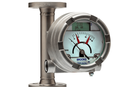
How does a rotameter work?
Rotameters or variable area flowmeters operate on the principle that the variation in the area of the flow stream required to produce a constant pressure differential is proportional to the flow rate.
The flowing fluid enters the bottom of the meter passes upward through a metering tube and around the float exiting at the top.
The flow rate is read by noting the position of the float against the calibrated scale etched on the glass.
Where do we take the reading?
With the flowmeters, the reading is taken at the center of the float.
It is recommended that the float be at eye level to minimize reading errors.
What is the difference between correlated and direct reading rotameters?
A direct reading flowmeter indicates the flow rate on its scale in specific engineering units (e.g. ml/min or scfh).
Direct reading scales are designed for a specific gas or liquid at a given temperature and pressure. While it is more convenient than a correlated flowmeter a direct reading flowmeter is less accurate and limited in its applications.
A correlated flowmeter is scaled along either a 65mm or a 150mm length from which a reading is taken. The reading is then compared to a correlation table for a specific gas or liquid.
This will give the actual flow in engineering units. One correlated flowmeter can be used with a variety of fluids or gases.
Can we use one flowmeter to measure different flow rates?
Yes. If a correlated flow tube is used different flow rates can be attained by using different floats i.e. carboloy, stainless steel, glass, or sapphire.
Must a rotameter be mounted vertically?
Generally, rotameters must be mounted vertically because the float must center itself in the fluid stream.
At high flow rates, the float assumes a position towards the tip of the metering tube, and at low flow rates positions itself lower in the tube.
Some of our rotameters have spring-loaded floats and therefore may be mounted in any orientation.
What are the advantages of using a variable area flowmeter?
- inexpensive
- somewhat self-cleaning
- no power required
- available in different materials for chemical compatibility
What are the limitations of using a variable area flowmeter?
- no output for data transmission
- sensitive to differing gas types and changes in temperature and pressure
Also Read : How to Select a Rotameter
Practical Flow Measurement Questions & Answers
Can we use a rotameter in a vacuum application or with back pressure?
Yes, but if you have a valve it must be placed at the outlet (top of the flowmeter). This is done by inverting the tube inside the frame and then turning over the frame.
At this position, the tube should read correctly from the original perspective and the valve should be at the outlet or top of the flowmeter. This allows for proper control of the vacuum.
What are the advantages and disadvantages of an insertion-type flowmeter?
Insertion meters typically have two parts: a flow sensor that is installed in the pipeline through a saddle, threaded inlet, or special in-line fitting, and the flow computer that displays the rate of flow and totalizes.
The advantages are many: Insertion meters are very cost-effective relative to pipe size, especially in 4″ or larger pipes. This is because two sizes of insertion sensors can cover from 2″ to 48″ pipes. These meters are also very easy to install.
The flow sensors can be mounted in vertical or horizontal pipes and normally only require a 1-1/2″ or 2″ NPT female inlet to the pipe. A hot-tap version of a flow sensor allows installation on a pressurized line as well as easy service without depressurization.
Insertion meters also offer the flexibility of use, since at any time a unit can be removed from one installation and reinstalled on another different-size pipeline by simply reprogramming the flow computer.
The various flow computers/display/transmitters offer many features such as 4-20 mA output, scaleable pulse outputs, programmable relays, and multiple inputs. Finally, these meters are easy to service – the flow sensor can usually be completely rebuilt in a few minutes without special tools.
The primary disadvantage is that insertion-type meters are not usually acceptable for billing purposes. Although these meters are very accurate, there is no AWWA standard and it is difficult to do precise testing and calibration as you would with a standard turbine meter that has test ports on it.
What kind of flowmeter will work for gravity flow, partially filled pipe applications?
An open channel flowmeter is the only truly reliable way to measure low-velocity gravity flow discharges that are usually partially filled pipe applications.
The use of an open channel flowmeter (OCF) requires some type of primary measuring device such as a flume or weir. In such a device, the rate of flow is directly proportional to the level of the water moving through the flume or weir.
The OCF measures flow by being programmed to recognize the type and size of the flume or weir (usually done by simply selecting from a built-in menu) and then converting that level to a rate of flow.
How can we measure the effluent from my plant, which flows by gravity to a lagoon through a pipe that is not full?
There are two ways to measure gravity flows in a partially full pipe. The most common is with an Open-Channel Flowmeter (OCF). This meter requires a primary measuring device such as a flume or weir.
The OCF is essentially a level device that calculates flows based on the characteristics of a particular flume or weir configuration. If you already have a standard flume or weir on your pipeline the OCF is the best choice, otherwise, you will have to consider the cost of installing such a primary device.
The other option is the Area Velocity Meter or AVM which is newer technology and gaining popularity. The AVM has a sensor unit that is installed in the pipeline (6″ or larger) and calculates flow by determining the depth and the velocity of the water in the pipe along with the area of the pipe cross-section.
The advantage of the AVM is that no primary device, flume or weir, is required.
There are other pros and cons to each type of flowmeter, so evaluate your system and ask questions before purchasing.
Also Read : Flowmeter Characteristics
How is an area velocity flowmeter (AVM) different from other flowmeters and where would I use one?
First, an area velocity flowmeter is one of the few flowmeters that will measure flow in a partially filled pipe or channel. This is perfect for gravity flow systems with possible solids in the water.
The AVM can be easily installed in the pipe at a manhole or even at the final discharge point. The AVM works by measuring two parameters: velocity and water depth in the pipe. The combination of these two measurements along with the pipe ID results in a fairly accurate flow measurement.
The AVFM is unique in that an ultrasonic sensor rather than a pressure sensor does the level measurement. It is the pressure-sensing device that has plagued many of the earlier AVM’s offered by other manufacturers.
Can we install my positive displacement meter on a vertical pipe?
Virtually all positive displacement meters require that they be installed on a horizontal plane. Installing these meters horizontally eliminates possible accuracy and excessive wear problems associated with a vertical installation.
If the only pipe available is a vertical pipe, a meter in-setter is often used. There are a variety of pipe connection options available for the different pipe materials, sizes, and types often used in household plumbing. Most can accommodate meters up to 1 inch in size.
If you already have a meter installed on a vertical pipe, a vertical to horizontal meter re-setter is often the solution. These devices have meter threads on the vertical portion of the unit to fit in place of the existing meter. They also have meter couplings to install the meter horizontally.
How do we test my remote mechanical register to make sure it is working properly?
The easiest way is test a mechanical remote is with a common 9-volt transistor battery. By removing the wires at the meter and gently brushing the two wires across the terminals of the battery, you are sending an electrical pulse through the wires energizing the remote and advancing the reading.
In addition, you are testing the continuity of the wire as well. If the numerals do not advance, go to the remote and try the same test again attaching two short wires to the terminals on the remote. If the numerals advance, the wire from the meter to the remote will need to be changed and If the numerals do not advance, the remote will need to be changed.
What is the general rule to follow when determining the proper installation location of a flow meter to obtain the greatest accuracy?
For the best accuracy results, the rule to follow is simple. Choose a place in the line to install the meter so that there are ten pipe diameters of straight pipe before (upstream) and five pipe diameters of straight pipe after (downstream) the meter location.
These lengths of pipe provide adequate time for the water to straighten out and pass uniformly through the meter and beyond, eliminating turbulence that may affect accuracy.
How do we determine the meter coupling size I need for my meters?
In the smaller household meters such as 5/8″ x 1/2″ and 5/8″ x 3/4″ sized meters, many manufacturers have 5/8 in the casting of each of the meter sizes, which makes it a little confusing.
The bore is 5/8″, but the diameter of the threads is different between the two-meter sizes. By measuring across the meter threads at the meter opening, you can easily determine the proper coupling size.
The diameter of the meter threads of a 5/8″ x 1/2″ meter will be 1″ and they are usually installed on a 1/2″ water service line.
The diameter of the meter threads on a 5/8″ x 3/4″ meter is 1-1/4″, and they are usually installed on a 3/4″ water service line.
We can’t or don’t want to cut my pipe. Which meter type can I use for dirty or wastewater and which meter can I use for drinking water?
With the single sensor mounted on the outside of the pipe, the meter of choice for a dirty or wastewater application is a Doppler meter.
The meter requires solids or bubbles in the liquid with a minimum size of 100 microns and a minimum concentration of 75 parts per million. The Doppler signal is bounced off of these particles to determine the flow rate within the pipe.
These meters work well on pipes made of PVC, carbon steel, cast iron, fiberglass, and lined pipe. Doppler signals cannot transmit through pipe walls, which contain air pockets like wood or loose pipe liners with an air gap between the pipe liner and the pipe wall.
For a drinking water quality application, the transit time flow meter is a good choice. They feature two non-intrusive sensors fixed to the pipe at pre-determined spacing based on pipe diameter and liquid characteristics.
The signal is transmitted between the sensors in the direction of liquid flow and then against the liquid flow. Since sound travels faster with the liquid flow than against it, a time differential is determined. The sound’s time of flight is accurately measured in both directions to calculate the flow rate.
When the time of flight in both directions is the same, the flow meter reads zero flow. These meters work better in cleaner liquids where particulates do not interfere with the signals being transmitted. These meters work on a wide variety of pipe materials.
Reference :
If you liked this article, then please subscribe to our YouTube Channel for Instrumentation, Electrical, PLC, and SCADA video tutorials.
You can also follow us on Facebook and Twitter to receive daily updates.
Read Next:
- Compare Different Flow Meters
- Instrumentation Engineer Guide
- Open Channel Flow Measurement
- Flow Meter Turndown Ratio
- Magnetic Flow Meter Animation







dear sir
could you help me I have application in natural gas flow and the location have to install flow meter on it is vertical and the flow direction from up to down?
what the best solution for this state
best regard
Basic requirements to installation of magnetic flow transmitter installation
How to calculate the linearity of ultrasonic flow meter?