Inst ToolsInst ToolsInst Tools
  • Ask
  • Courses
  • Videos
  • Q & A
    • Interview
      • Instrumentation
      • Electronics
      • Electrical
      • Practical Questions
    • MCQ
      • Instrumentation MCQ
      • Electrical MCQ
      • Electronics MCQ
      • Control Systems MCQ
      • Analog Electronics MCQ
      • Digital Electronics MCQ
      • Power Electronics MCQ
      • Microprocessor MCQ
      • Multiple Choice Questions
  • EE
    • Electronics
      • Electronics Q & A
      • Electronic Basics
      • Electronic Devices & Circuits
      • Electronics Animation
      • Digital Electronics
    • Electrical
      • Electrical Basics
      • Electrical Q & A
      • Power Electronics
      • Electrical Machines
      • Electrical Animation
      • Power Systems
      • Switchgear & Protection
      • Transmission & Distribution
  • Measure
    • Control Valves
    • Calibration
    • Temperature
    • Pressure
    • Flow
    • Level
    • Analyzers
    • Switches
    • Vibration
    • Solenoid Valve
  • Control
    • PLC Tutorials
    • Control Systems
    • Safety Instrumented System (SIS)
    • Communication
    • Fire & Gas System
  • More
    • Design
    • Tools
    • Animation
    • Basics
    • Formulas
    • Standards
    • TextBooks
    • Common
    • Software
    • Excel Tools
    • Erection & Commissioning
    • Process Fundamentals
    • Videos
    • Books
Search
All rights reserved. Reproduction in whole or in part without written permission is prohibited.
Reading: Field Instrument Calibration Errors
Share
Notification Show More
Font ResizerAa
Inst ToolsInst Tools
Font ResizerAa
  • Courses
  • PLC Tutorials
  • Control Systems
Search
  • Ask
  • Courses
  • Videos
  • Q & A
    • Interview
    • MCQ
  • EE
    • Electronics
    • Electrical
  • Measure
    • Control Valves
    • Calibration
    • Temperature
    • Pressure
    • Flow
    • Level
    • Analyzers
    • Switches
    • Vibration
    • Solenoid Valve
  • Control
    • PLC Tutorials
    • Control Systems
    • Safety Instrumented System (SIS)
    • Communication
    • Fire & Gas System
  • More
    • Design
    • Tools
    • Animation
    • Basics
    • Formulas
    • Standards
    • TextBooks
    • Common
    • Software
    • Excel Tools
    • Erection & Commissioning
    • Process Fundamentals
    • Videos
    • Books
Follow US
All rights reserved. Reproduction in whole or in part without written permission is prohibited.
Inst Tools > Blog > Calibration > Field Instrument Calibration Errors

Field Instrument Calibration Errors

Last updated: January 26, 2020 11:18 pm
Editorial Staff
Calibration
3 Comments
Share
6 Min Read
SHARE

The efficient identification and correction of instrument calibration errors is an important function for instrument technicians. For some technicians – particularly those working in industries where calibration accuracy is mandated by law – the task of routine calibration consumes most of their working time.

Contents
Typical calibration errorsZero Shift Calibration ErrorSpan Shift Calibration ErrorLinearity Calibration ErrorHysteresis Calibration ErrorPractical Problems

For other technicians calibration may be an occasional task, but nevertheless these technicians must be able to quickly diagnose calibration errors when they cause problems in instrumented systems. This section describes common instrument calibration errors and the procedures by which those errors may be detected and corrected.

Typical calibration errors

The slope-intercept form of a linear equation describes the response of any linear instrument:

y = mx + b

Where,
y = Output
m = Span adjustment
x = Input
b = Zero adjustment

Zero Shift Calibration Error

A zero shift calibration error shifts the function vertically on the graph, which is equivalent to altering the value of b in the slope-intercept equation. This error affects all calibration points equally, creating the same percentage of error across the entire range.

Using the same example of a pressure transmitter with 0 to 100 PSI input range and 4 to 20 mA output range:zero shift calibration error

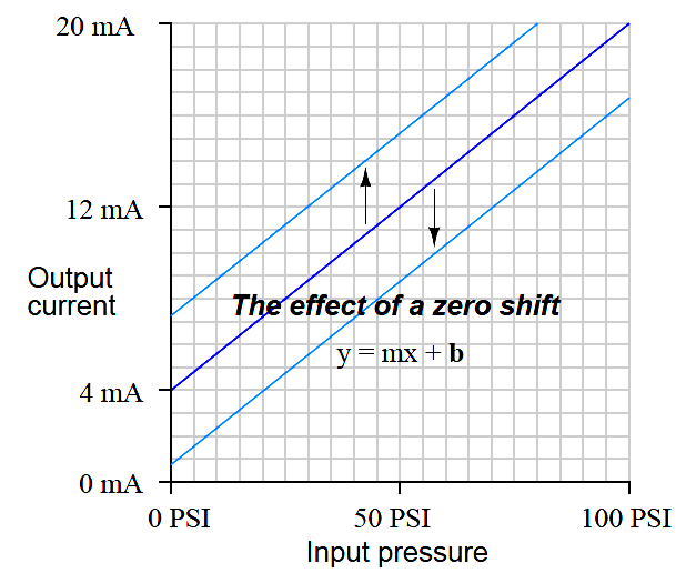
If a transmitter suffers from a zero calibration error, that error may be corrected by carefully moving the “zero” adjustment until the response is ideal, essentially altering the value of b in the linear equation.

Span Shift Calibration Error

A span shift calibration error shifts the slope of the function, which is equivalent to altering the value of m in the slope-intercept equation. This error’s effect is unequal at different points throughout the range:

Span Shift Calibration Error

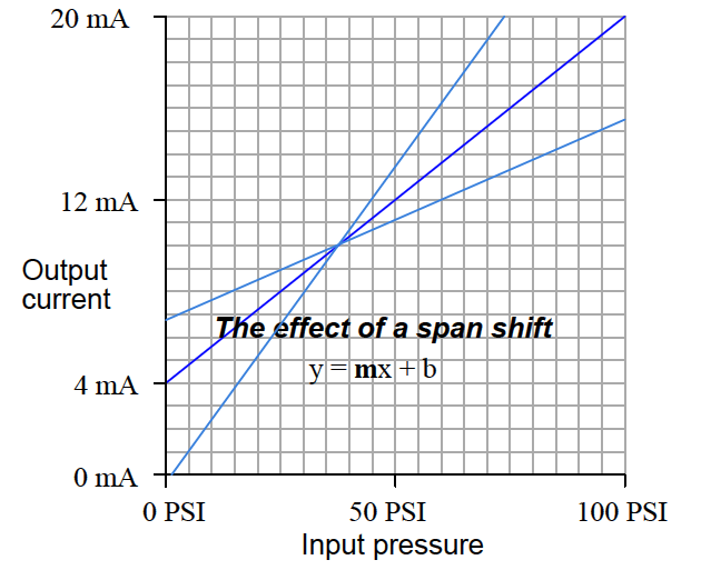
If a transmitter suffers from a span calibration error, that error may be corrected by carefully moving the “span” adjustment until the response is ideal, essentially altering the value of m in the linear equation.

Linearity Calibration Error

A linearity calibration error causes the instrument’s response function to no longer be a straight line. This type of error does not directly relate to a shift in either zero (b) or span (m) because the slope-intercept equation only describes straight lines:

Linearity Calibration Error

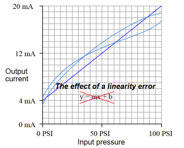
Some instruments provide means to adjust the linearity of their response, in which case this adjustment needs to be carefully altered.

The behavior of a linearity adjustment is unique to each model of instrument, and so you must consult the manufacturer’s documentation for details on how and why the linearity adjustment works.

If an instrument does not provide a linearity adjustment, the best you can do for this type of problem is “split the error” between high and low extremes, so the maximum absolute error at any point in the range is minimized.

Hysteresis Calibration Error

A hysteresis calibration error occurs when the instrument responds differently to an increasing input compared to a decreasing input. The only way to detect this type of error is to do an up-down calibration test, checking for instrument response at the same calibration points going down as going up:

Hysteresis Calibration Error

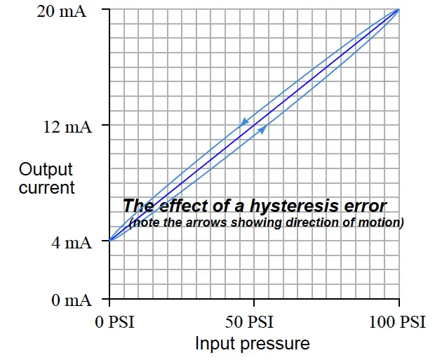
Hysteresis errors are almost always caused by mechanical friction on some moving element (and/or a loose coupling between mechanical elements) such as bourdon tubes, bellows, diaphragms, pivots, levers, or gear sets.

Friction always acts in a direction opposite to that of relative motion, which is why the output of an instrument with hysteresis problems always lags behind the changing input, causing the instrument to register falsely low on a rising stimulus and falsely high on a falling stimulus.

Flexible metal strips called flexures – which are designed to serve as frictionless pivot points in mechanical instruments – may also cause hysteresis errors if cracked or bent.

Thus, hysteresis errors cannot be rectified by simply making calibration adjustments to the instrument – one must usually replace defective components or correct coupling problems within the instrument mechanism.

Practical Problems

In practice, most calibration errors are some combination of zero, span, linearity, and hysteresis problems. An important point to remember is that with rare exceptions, zero errors always accompany other types of errors.

In other words, it is extremely rare to find an instrument with a span, linearity, or hysteresis error that does not also exhibit a zero error.

For this reason, technicians often perform a single-point calibration test of an instrument as a qualitative indication of its calibration health. If the instrument performs within specification at that one point, its calibration over the entire range is probably good. Conversely, if the instrument fails to meet specification at that one point, it definitely needs to be recalibrated.

A very common single-point test for instrument technicians to perform on differential pressure (“DP”) instruments is to close both block valves on the three-valve manifold assembly and then open the equalizing valve, to produce a known condition of 0 PSI differential pressure:

Differential Pressure Transmitter Manifold

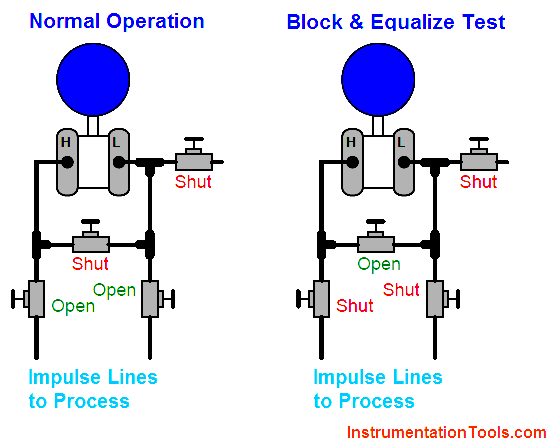
Most DP instrument ranges encompass 0 PSI, making this a very simple single-point check. If the technician “blocks and equalizes” a DP instrument and it properly reads zero, its calibration is probably good across the entire range. If the DP instrument fails to read zero during this test, it definitely needs to be recalibrated.

Don't Miss Our Updates
Be the first to get exclusive content straight to your email.
We promise not to spam you. You can unsubscribe at any time.
Invalid email address
You've successfully subscribed !
Calibration : Up-tests and Down-tests
Solenoid Valve Functional Testing
Capacitance Level Sensor Principle, Limitations, Installation & Calibration
Instrument Turndown Ratio
Smart Transmitter Calibration Tutorial Part 1
Share This Article
Facebook Whatsapp Whatsapp LinkedIn Copy Link
Share
3 Comments
  • Rodolfo redovan says:
    August 16, 2016 at 5:17 pm

    I do this on steam drum level

    Reply
  • jayesh says:
    June 22, 2017 at 6:04 am

    Please give me calibration formula of DP type flow transmitter please sir

    Reply
  • Allaoua says:
    February 5, 2023 at 11:50 pm

    Interesting web site for instrumentation team members

    Reply

Leave a Reply Cancel reply

Your email address will not be published. Required fields are marked *

Stay Connected

128.3kFollowersLike
69.1kFollowersFollow
208kSubscribersSubscribe
38kFollowersFollow

Categories

Recent Comments

  • Kamli on Top Free PLC Software
  • Guifty Shimica on Top Non-PLC Certification Courses for Automation Professionals
  • Guifty Shimica on Top Non-PLC Certification Courses for Automation Professionals
  • MIHARITSOA Aina Sitraka on Top Non-PLC Certification Courses for Automation Professionals

Related Articles

Gas Detectors Bump Testing

What is Bump Testing ?

Calibrate Eddy Current Conductivity Instrument

How to Calibrate the Eddy Current Conductivity Meter?

Uncertainty Calculations of Pressure Calibration

Uncertainty Calculations of Pressure Calibration

Closed-tank-DP-Level-Transmitter-with-wet-leg-Zero-elevation-Calibration

Closed tank DP Level Transmitter with wet leg Zero elevation Calibration

Pressure Safety Valves Functional Testing

Pressure Safety Valves Functional Testing

Fieldbus Flow Transmitter Configuration

Fieldbus Flow Transmitter Configuration

Why Calibration is Important

Why Calibration is Important?

Specific-Conductance-Calibration-Procedure

Specific Conductance Calibration Procedure

More Articles

Siemens S7-200 PLC

Programmable Logic Controller (PLC) Questions and Answers – 13

Temperature Measurement Questions

Interview Questions on Temperature Measurement

Maintenance Override Switch (MOS)

What is Maintenance Override Switch (MOS) ?

Control Valve in PlantPAx Project

Configuration of Control Valve in Studio 5000

Pump Mechanical Seal and thrust bearing Problem

Pump 3-monthly Seal Leaks threaten entire Plant Shut down Indefinitely

Zener Diode Voltage Regulator Operation

Zener Diode Voltage Regulator Operation

What is a Bus Coupler in Electrical Panel

What is a Bus Coupler in Electrical Panel?

Digital Electronics Multiple Choice Questions

MOS Digital Integrated Circuits Objective Questions

Follow US
All rights reserved. Reproduction in whole or in part without written permission is prohibited.
Welcome Back!

Sign in to your account

Username or Email Address
Password

Lost your password?