This article is about the FB block which we use in Siemens PLC programming.
Function block (FB) is used to make the programming task easier. It is like subroutine which we have seen in Allen-Bradley PLC.
To stop writing the program over and over, it is a good practice to write the program in Function Block and call that program on-demand from OB.
The function block is configured to accept input from the main OB and write the output based on the execution of the FB.
FB is like FC with one difference in that is FC has overall memory space and doesn’t require any extra block to store that value whereas in FB it requires DB (Data Block) to store values. For each new FB, a new DB is required.
To understand how FB works, I will explain it using a simple example.
FB Block PLC Programming
Let’s first learn how to create FB, to do that so follow the below steps.
- Open the TIA PORTAL environment.
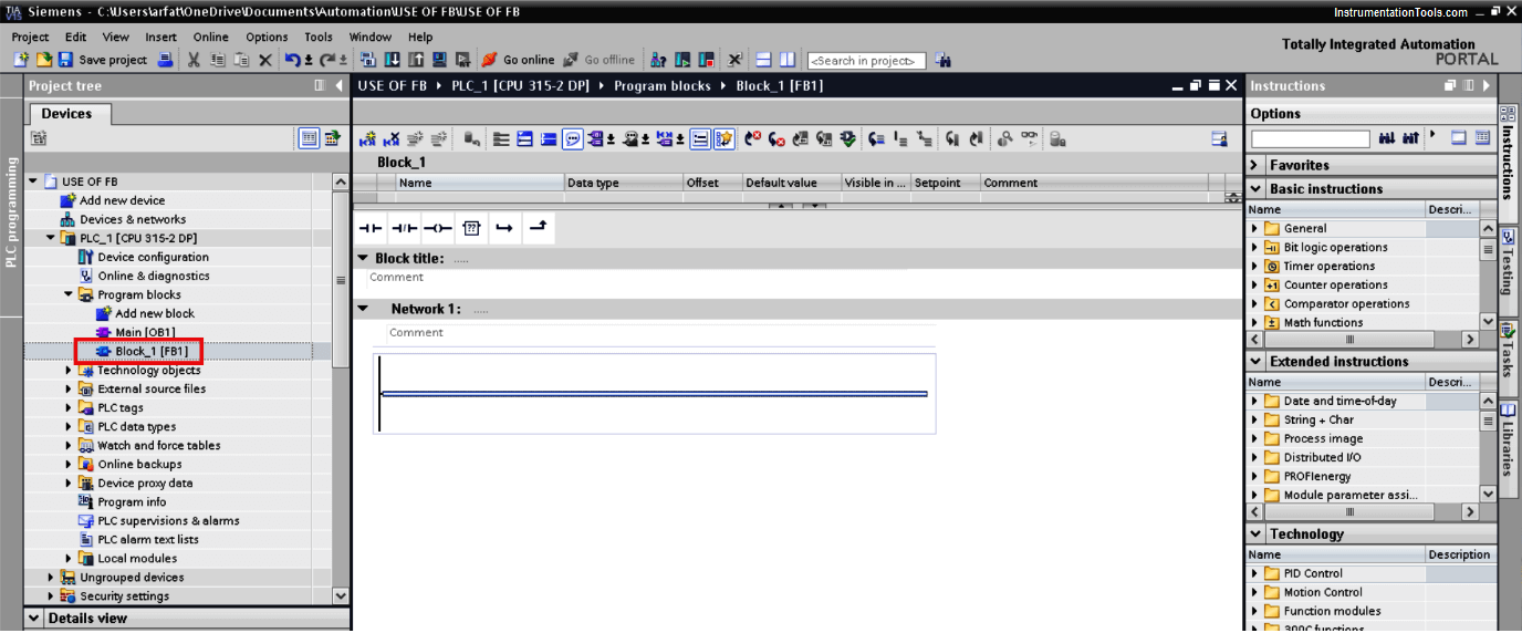
- Go to “PLC programming” and select “Function Block” and click on “add”.
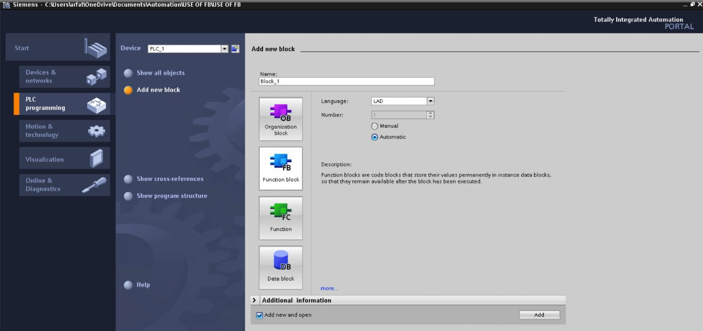
- The following window will pop-up, you can see here in the red square new block is added.
Let, write PLC program for pet bottling process, where a bottle is getting rejected due to some issue like the cap is torn, weight is less or the cap is not properly fitted, etc.
The rejected bottle is automatically sent to the rejection conveyor. Now rejection ratio is too higher which fills till a proximity sensor activates in terms of sound alarm.
Let, assume we have 4 to 5 same rejection conveyor and I want to write the program. Now instead of writing the same logic over and over I will write the program in FB and call each time when OB executes.
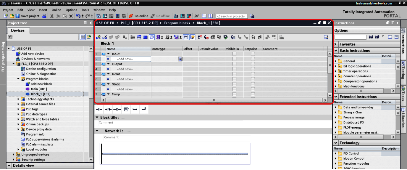
- Here in the FB environment, you can find different options to write input and output as you can show in the figure.
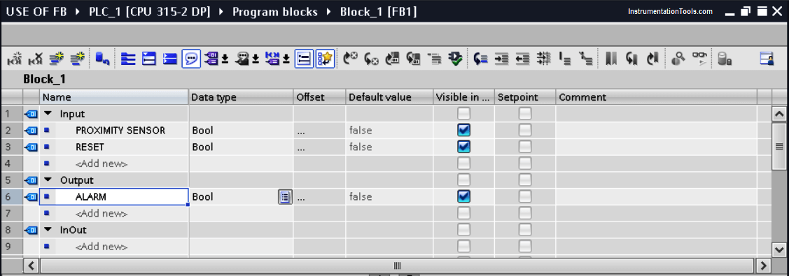
- For our example, let consider 2 inputs and one output for alarm as shown in the below window.
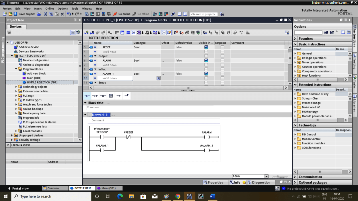
- In the below window you can see the program which I have written for rejection conveyor. Each time conveyor fills, the proximity sensor will turn ON which results in turning ON alarm.
A reset button is used to reset the alarm. Here, I have used alarm_1 as a latching in both input and output side because you can’t define output ALARM as input in FB block.
- To insert/add the above logic into the main OB we simply have to open the OB environment and have to drag FB block to OB.
As soon as you move FB to OB you will receive a pop-up as shown in the below window.
Here, you have to define the DB block as a memory space of FB. Click on “ok” to add DB.
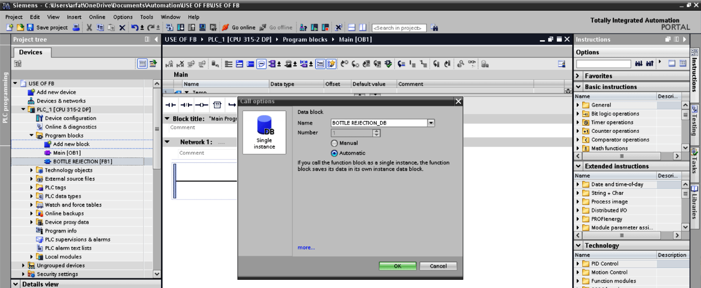
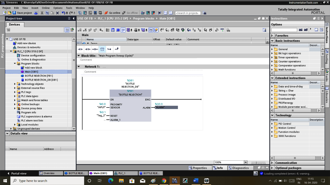
- Here, by hitting ok the program will be added to OB as shown in the below window.

- Define input and output. Whenever OB is executed it will call FB and Alarm will generate.
We can add other conveyor’s input and output here and each time any input gets activated, it will call FB and alarm will sound. Resetting the output will reset the alarm.
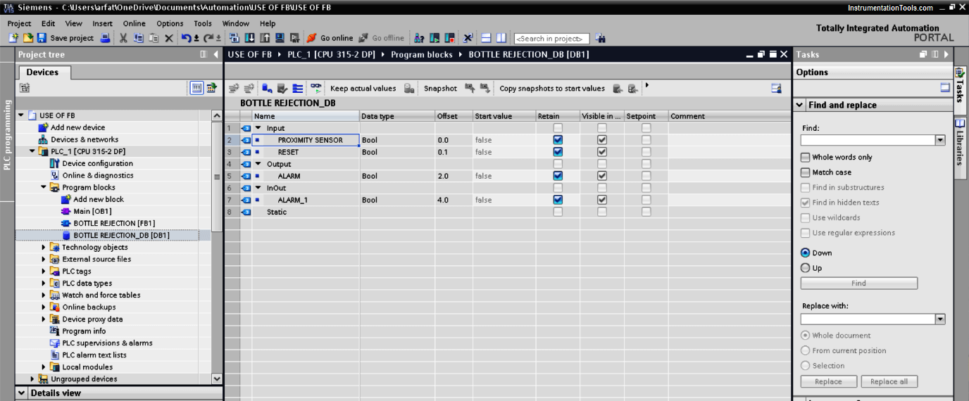
- Here, you can see how DB looks like. Db here will store the value of the FB.
Author: Suhel Patel
If you liked this article, then please subscribe to our YouTube Channel for PLC and SCADA video tutorials.
You can also follow us on Facebook and Twitter to receive daily updates.
Read Next:
- Ladder Logic Examples
- PLC, HMI, VFD, and Motor
- Pulse Generation using Timer
- Liquid Mixing PLC Logic
- Alarm Acknowledge PLC

