This article will discuss the use of various COUNTER instructions in the Omron PLC. Counter instructions are functions used to count the number of specific signals or events (such as input pulses, sensor condition changes, or machine operations) and produce an output when the count reaches a predetermined value. In the CX-Programmer software, there are four types of Counter Instructions (CNT, CNTX, CNTR, and CNTRX). Each instruction will activate a specific output (e.g., a lamp) when the counter data reaches the predefined set value parameter.
Program Objective
Here we discussed different counters in the Omron PLC.
CNT Instruction
The CNT instruction is a Decrement counter instruction with a maximum counter SV (Set Value) of “9999”.
This instruction counts counter data in BCD (Binary Coded Decimal) format, so the SV parameter must begin with the syntax “#”.
The CNT instruction has two input parameters: one to decrement the PV (Present Value) of the counter, and one to reset the PV.
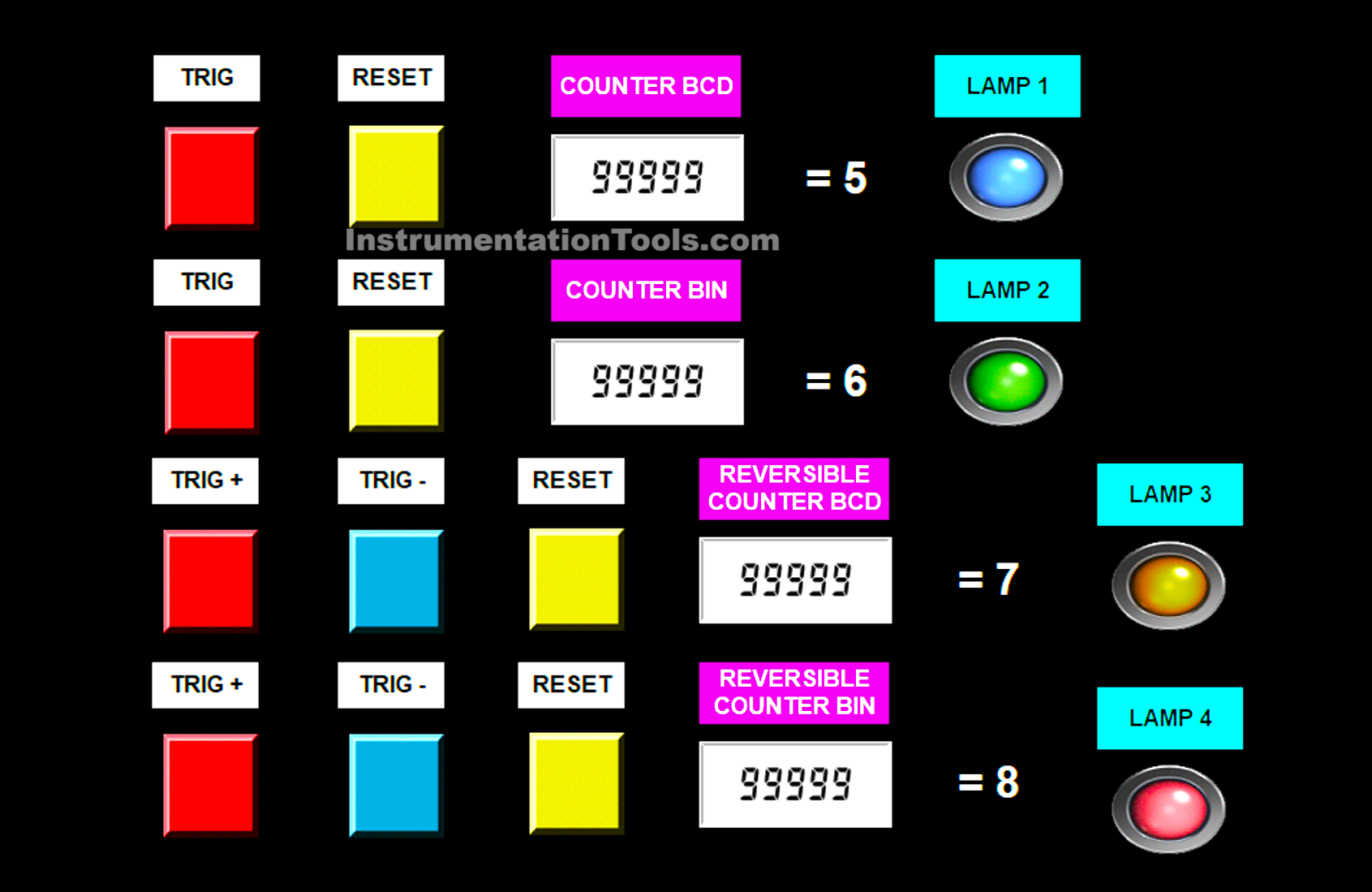
In this instruction, the counter SV is set to “#5”, and it will activate Lamp 1 after receiving a trigger five times.
CNTX(546) Instruction
The CNTX instruction is a Decrement counter instruction with a maximum SV of “65535” in decimal format and “#FFFF” in hexadecimal format.
The SV parameter must begin with the syntax “&” if written in decimal, and with “#” if written in hexadecimal. The CNTX instruction has two input parameters: one to decrement the PV and one to reset it.
In this instruction, the counter SV is set to “&6”, and it will activate Lamp 2 after receiving a trigger six times.
CNTR(012) Instruction
The CNTR is a counter instruction that can increment and decrement the PV with a maximum SV of “9999”. This instruction counts counter data in BCD (Binary Coded Decimal) format, so the SV must be written with the “#” syntax.
The CNTR instruction has three input parameters: one to decrement, one to increment, and one to reset the PV.
In this instruction, the SV is set to “#7”, and it will activate Lamp 3 after receiving a trigger more than seven times.
CNTRX(548) Instruction
The CNTRX is a counter instruction that can increment and decrement the PV with a maximum SV of “65535” in decimal or “#FFFF” in hexadecimal.
The SV parameter must begin with “&” if in decimal format, and with “#” if in hexadecimal format. The CNTRX instruction has three input parameters: one to decrement, one to increment, and one to reset the PV.
In this instruction, the SV is set to “&8”, and it will activate Lamp 4 after receiving a trigger more than eight times.
PLC Simulation Video
In the video below, we simulated the PLC program with an HMI screen and results displayed.
Example of Using a Counter
IO Mapping
| S.No. | Comment | Input (I) | Output(Q) | COUNTER |
|---|---|---|---|---|
| 1 | TRIG_CNT_BCD | 0.00 | ||
| 2 | RES_CNT_BCD | 0.01 | ||
| 3 | TRIG_CNT_BIN | 0.02 | ||
| 4 | RES_CNT_BIN | 0.03 | ||
| 5 | +CNTR_BCD | 0.04 | ||
| 6 | -CNTR_BCD | 0.05 | ||
| 7 | RES_CNTR | 0.06 | ||
| 8 | +CNTRX_BIN | 1.00 | ||
| 9 | -CNTRX_BIN | 1.01 | ||
| 10 | RES_CNTRX | 1.02 | ||
| 11 | OUT1 | 100.00 | ||
| 12 | OUT2 | 100.01 | ||
| 13 | OUT3 | 100.02 | ||
| 14 | OUT4 | 100.03 | ||
| 15 | COUNTER_BCD | C000 | ||
| 16 | COUNTER_BIN | C001 | ||
| 17 | COUNTER_BCD_REVERSIBLE | C002 | ||
| 18 | COUNTER_BIN_REVERSIBLE | C003 |
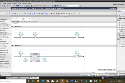
Omron PLC (CX-Programmer)
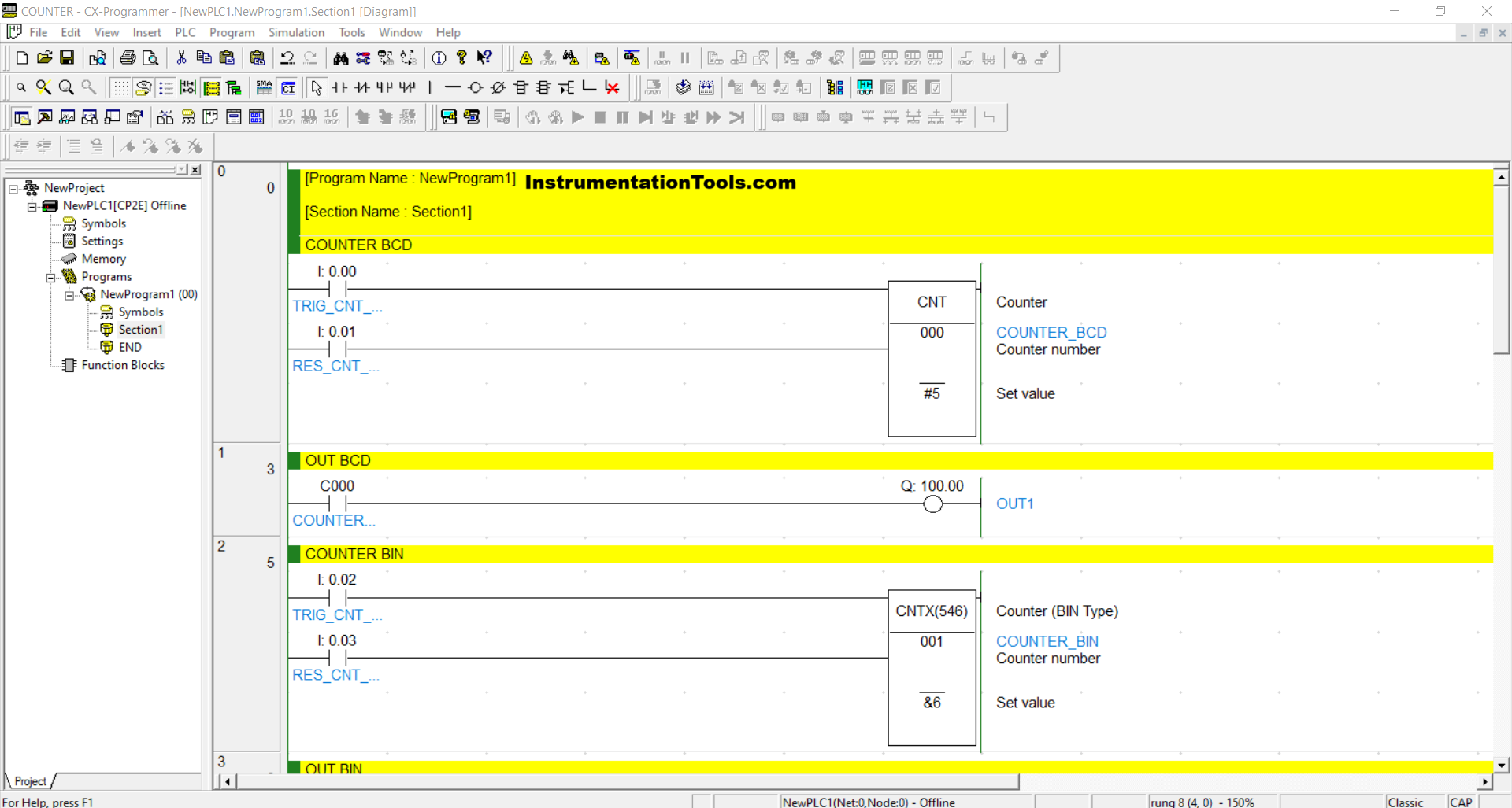
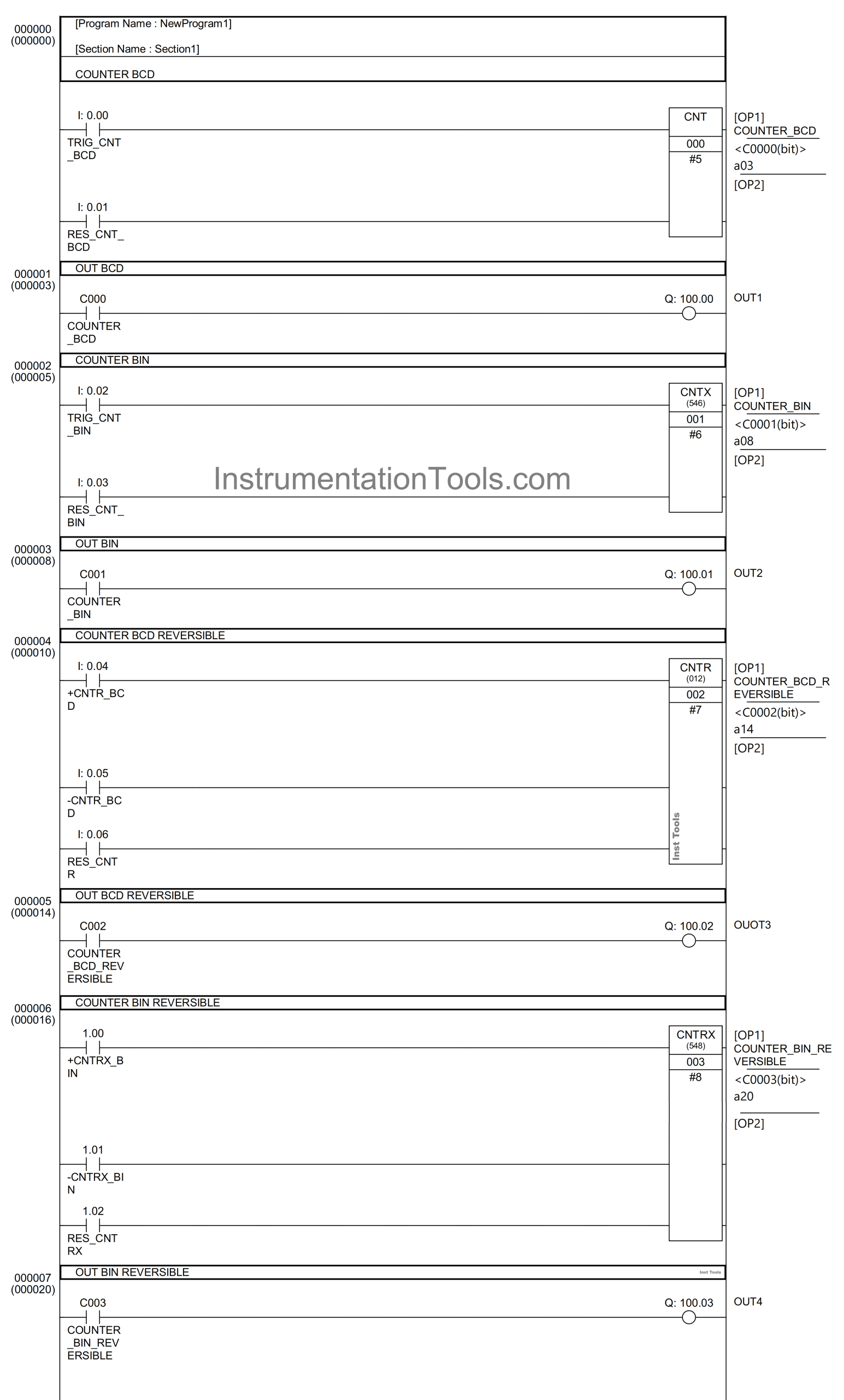
RUNG 0 (COUNTER BCD)
In this Rung, if the TRIG_CNT_BCD (0.00) button is pressed, the value in the counter memory COUNTER_BCD (C000) will increase (+1). When the value in the counter memory COUNTER_BCD (C000) is Equal To “0” then the CNT Instruction will be ON.
And if the RES_CNT_BCD (0.01) button is pressed, the value in the counter memory COUNTER_BCD (C000) will be reset to “#5”.
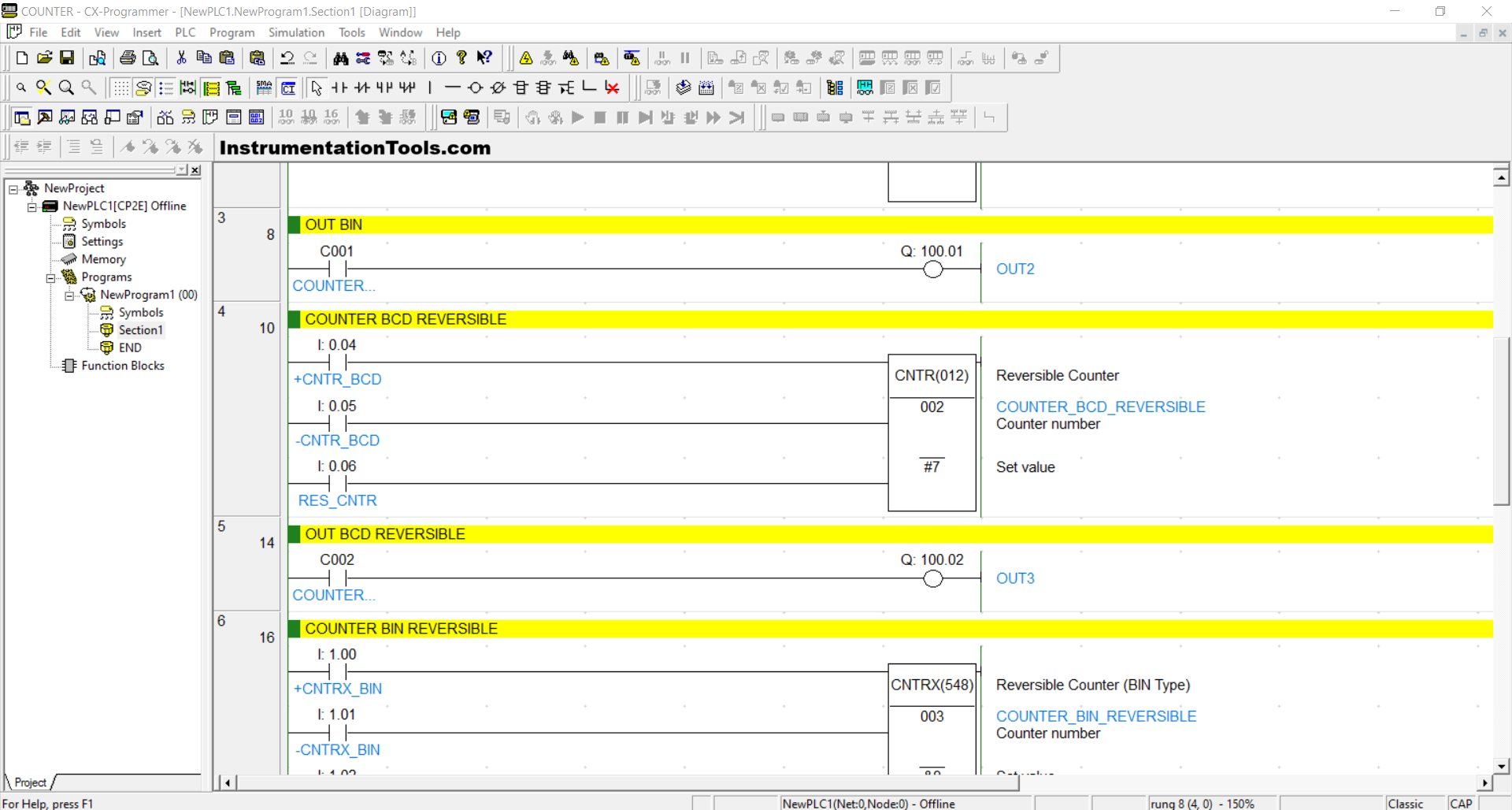
RUNG 1 (OUT BCD)
In this Rung, the output OUT1 (100.00) will be ON if the NO contact of COUNTER_BCD (C000) is in the HIGH state.
RUNG 2 (COUNTER BIN)
In this Rung, if the TRIG_CNT_BIN (0.02) button is pressed, then the value in the counter memory COUNTER_BIN (C001) will increase (+1). When the value in the counter memory COUNTER_BIN (C001) is Equal To “0 then the CNTX(546) instruction will be ON.
And if the RES_CNT_BIN (0.03) button is pressed, then the value in the counter memory COUNTER_BIN (C001) will be reset to “&6”.
RUNG 3 (OUT BIN)
In this Rung, the output OUT2 (100.01) will be ON if the NO contact of COUNTER_BIN (C001) is in HIGH state.
RUNG 4 (COUNTER BCD REVERSIBLE)
In this Rung, if the +CNTR_BCD (0.04) button is pressed, then the value in the counter memory COUNTER_BCD_ REVERSIBLE (C002) will increase (+1). And if the -CNTR_BCD (0.05) button is pressed, then the value in the counter memory COUNTER_BCD_ REVERSIBLE (C002) will decrease (-1).
When the value in the counter memory COUNTER_BCD_ REVERSIBLE (C002) is Exceeds “#7” then the CNTR(012) instruction will be ON.
And if the RES_CNTR (0.06) button is pressed, then the value in the counter memory COUNTER_BCD_ REVERSIBLE (C002) will be reset to zero “0”.
RUNG 5 (OUT BCD REVERSIBLE)
In this Rung, the output OUT3 (100.02) will be ON if the NO contact of COUNTER_BCD (C002) is in the HIGH state.
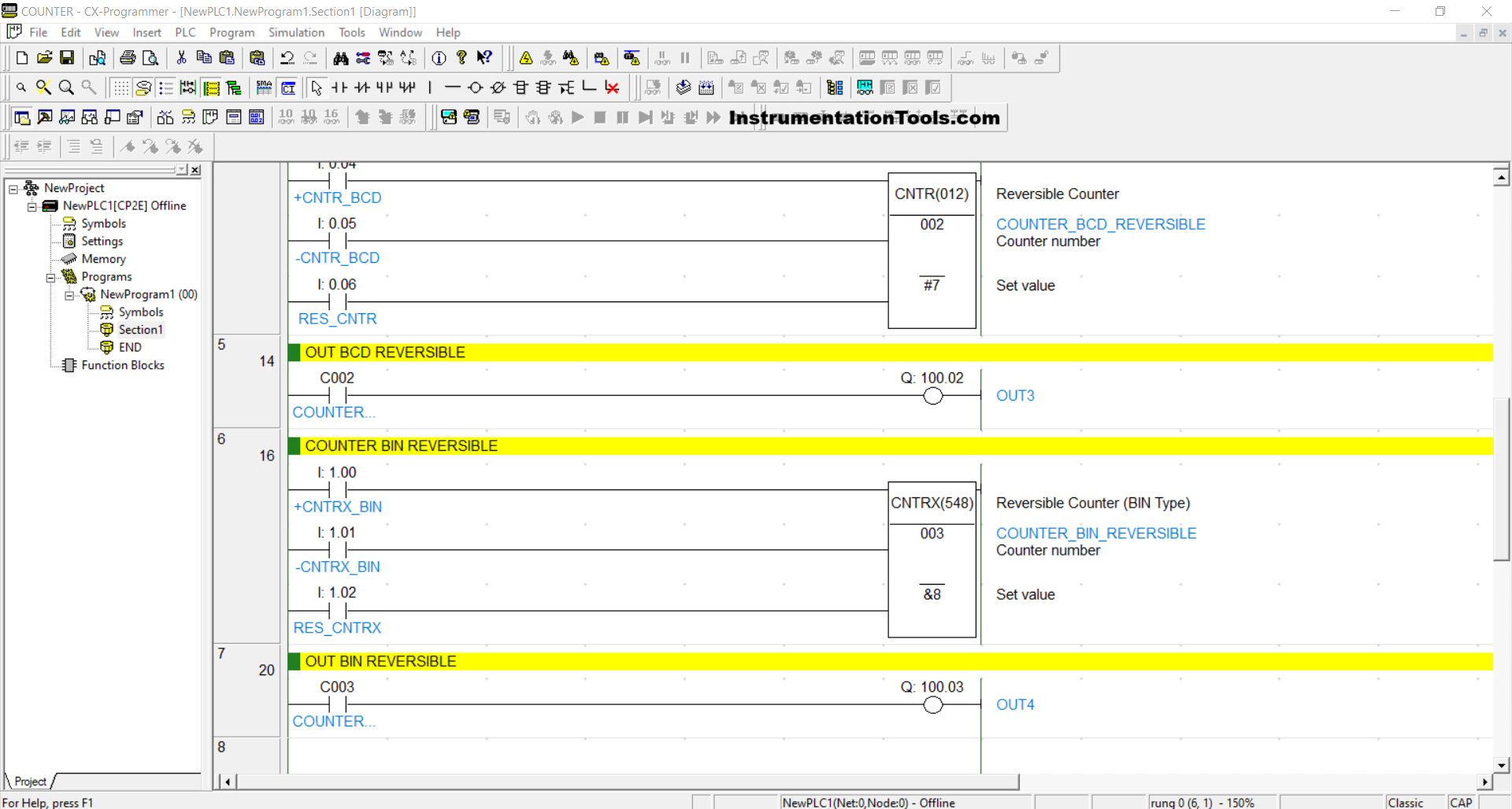
RUNG 6 (COUNTER BIN REVERSIBLE)
In this Rung, if the +CNTR_BIN (1.00) button is pressed, then the value in the counter memory COUNTER_BIN_ REVERSIBLE (C003) will increase (+1). And if the -CNTR_BIN (1.01) button is pressed, then the value in the counter memory COUNTER_BIN_ REVERSIBLE (C003) will decrease (-1).
When the value in the counter memory COUNTER_BIN_REVERSIBLE (C003) is Exceeds “&8” then the CNTRX(548) instruction will be ON.
And if the RES_CNTRX (1.02) button is pressed, then the value in the counter memory COUNTER_BIN_ REVERSIBLE (C003) will be reset to zero “0”.
RUNG 7 (OUT BIN REVERSIBLE)
In this Rung, output OUT4 (100.03) will be ON if the NO contact of COUNTER_BIN (C003) is in HIGH state.
Read Next:
- Siemens Motor PLC Programming Example
- Tank Farm Management PLC Programming
- EasyBuilder Pro Online Simulation of PLC
- Increment & Decrement Instructions
- Learn Instrumentation & Control Systems