Inst ToolsInst ToolsInst Tools
  • Courses
  • Automation
    • PLC
    • Control System
    • Safety System
    • Communication
    • Fire & Gas System
  • Instrumentation
    • Design
    • Pressure
    • Temperature
    • Flow
    • Level
    • Vibration
    • Analyzer
    • Control Valve
    • Switch
    • Calibration
    • Erection & Commissioning
  • Interview
    • Instrumentation
    • Electrical
    • Electronics
    • Practical
  • Q&A
    • Instrumentation
    • Control System
    • Electrical
    • Electronics
    • Analog Electronics
    • Digital Electronics
    • Power Electronics
    • Microprocessor
  • Request
Search
  • Books
  • Software
  • Projects
  • Process
  • Tools
  • Basics
  • Formula
  • Power Plant
  • Root Cause Analysis
  • Electrical Basics
  • Animation
  • Standards
  • 4-20 mA Course
  • Siemens PLC Course
Reading: How to Use Encode and Decode Instructions in PLC ?
Share
Font ResizerAa
Inst ToolsInst Tools
Font ResizerAa
  • Courses
  • Design
  • PLC
  • Interview
  • Control System
Search
  • Courses
  • Automation
    • PLC
    • Control System
    • Safety System
    • Communication
    • Fire & Gas System
  • Instrumentation
    • Design
    • Pressure
    • Temperature
    • Flow
    • Level
    • Vibration
    • Analyzer
    • Control Valve
    • Switch
    • Calibration
    • Erection & Commissioning
  • Interview
    • Instrumentation
    • Electrical
    • Electronics
    • Practical
  • Q&A
    • Instrumentation
    • Control System
    • Electrical
    • Electronics
    • Analog Electronics
    • Digital Electronics
    • Power Electronics
    • Microprocessor
  • Request
Follow US
All rights reserved. Reproduction in whole or in part without written permission is prohibited.
Inst Tools > Blog > PLC Tutorials > How to Use Encode and Decode Instructions in PLC ?

How to Use Encode and Decode Instructions in PLC ?

Last updated: March 4, 2021 3:01 pm
Editorial Staff
PLC Tutorials
No Comments
Share
4 Min Read
SHARE

In this article, we discussed Encode (ENC) and Decode (DCD) Instructions application in PLC ladder logic with example programs.

Contents
Encode and Decode InstructionsENCODING (ENC)DECODING (DCD)PLC ProgramProgram DescriptionEXAMPLE 1 :EXAMPLE 2:Conclusion:

In telecommunication, multiple analog and digital signals are combined into one signal over a shared medium. The multiplexed signal is transmitted over a communication channel such as a cable.

The multiplexing divides the capacity of the communication channel into several logical channels, one for each message signal or data stream to be transferred.

A reverse process, known as demultiplexing, extracts the original channels on the receiver end.

Encode and Decode Instructions
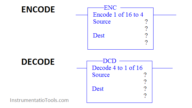
Encode and Decode Instructions in PLC

ENCODING (ENC)

Source is the address of the word to be encoded. Only one bit of this word should be on at any one time.

If more than one bit in the source is set, the destination bits will be set based on the least significant bit that is set. If a source of zero is used, all of the destination bits will be reset and the zero bit will be set.

Destination is the address that contains the bit encode information. Bits 4 -15 of the destination are reset by the ENC instruction.

DECODING (DCD)

Use DCD output instruction to multiplex data for applications such as rotary switches, keypads, bank switching, etc.

When rung conditions are true, the DCD instruction decodes a 4-bit value (0-16) in the source word and turns on a bit in the destination word that corresponds to the decoded value.

Source is the address that contains the bit decode information. Only the first four bits (0-3) are used. The remaining bits may be used for other application specific needs. Change the value of the first four bits of this word to select one bit of the destination word.

Destination is the address of the word to be decoded. Only one bit of this word is turned on at any one time, depending on the value of the source word,

PLC Program
How to Use Encode and Decode Instructions in PLC

Program Description

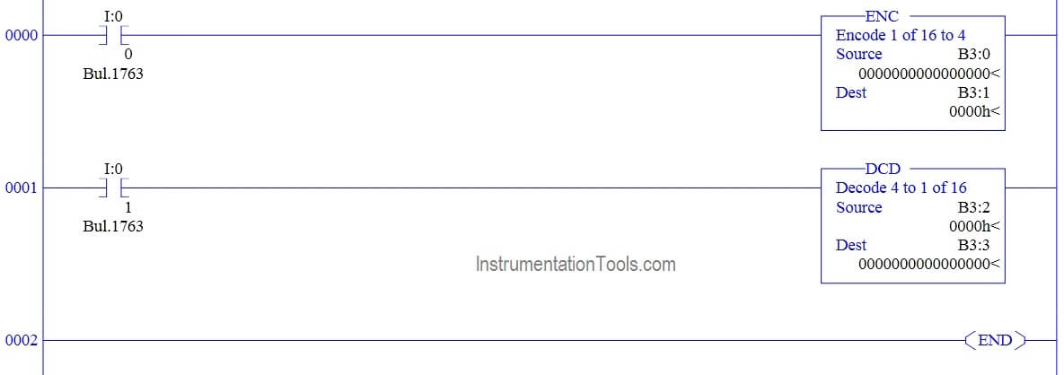
  1. RUNG 000 – I:0/0 is used to enable the rung condition, ENC block is used to encode the data from B3:0 and store the result in B3:1.
  2. RUNG 001 – I:0/1 is used to enable the rung condition, DCD block is used to decode the data from B3:2 and store the result in B3:3.

EXAMPLE 1 :

ENCODING

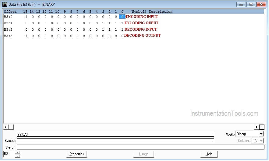
SOURCE : B3:0-1000000000000000  (Any one bit of 16 bit enable to change last four bit of  data in destination address)

DESTINATION : B3:1-0000000000001111

DECODING

SOURCE : B3:2-0000000000001111 (Last four bit in source data will change the 16bit data in the destination address)

DESTINATION : B3:3-1000000000000000
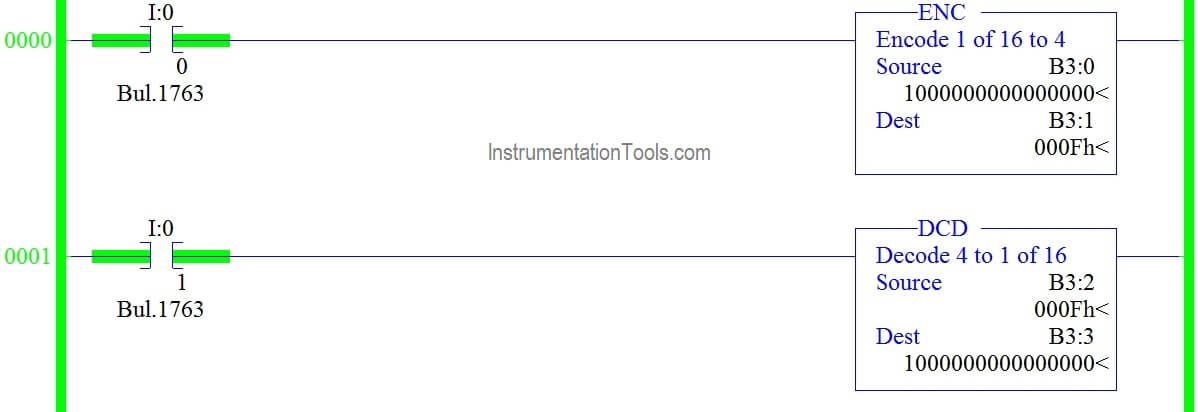
ENC DCD Instructions in Ladder Logic

DATA FILE OUTPUT

Data File Output of Encode Decode Logic

EXAMPLE 2:

ENCODING

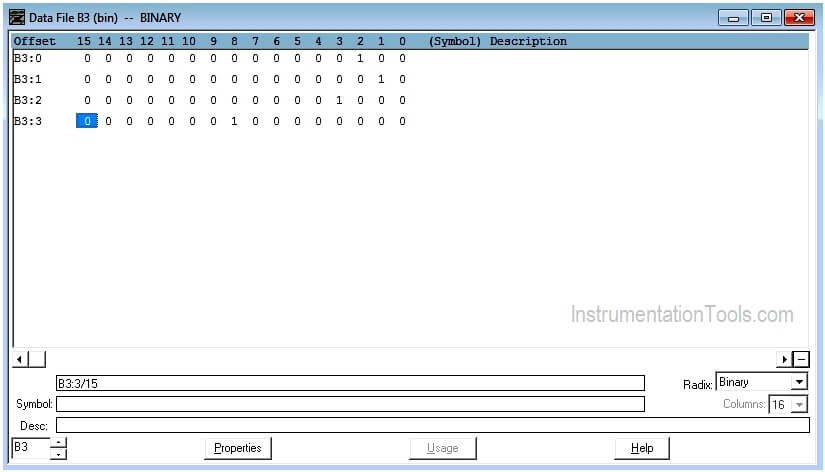
SOURCE : B3:0-0000000000000100  (Any one bit of 16 bit enable to change last four bit of  data in destination address)

DESTINATION : B3:1-0000000000000010

DECODING

SOURCE : B3:2-0000000000001000 (Last four bit in source data will change the 16bit data in the destination address)

DESTINATION : B3:3-0000000100000000
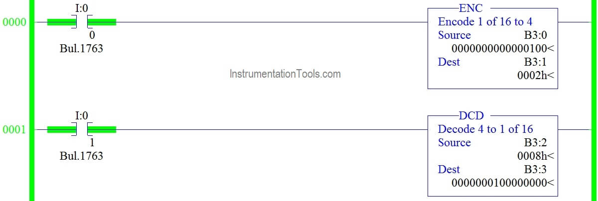
Example of Encode and Decode PLC Programs

DATA FILE OUTPUT

Output of Decode and Encode Ladder Logic

Conclusion:

The above-explained Encode/Decode is for example only. It may vary from real-time.

Author: Hema Sundaresan

If you liked this article, then please subscribe to our YouTube Channel for PLC and SCADA video tutorials.

You can also follow us on Facebook and Twitter to receive daily updates.

Read Next:
How to Control VFD with PLC

Convert V to I using Resistor

Logical Instructions in PLC

Flow Meter Totalizer logic

PLC based Car Wash Program

Don't Miss Our Updates
Be the first to get exclusive content straight to your email.
We promise not to spam you. You can unsubscribe at any time.
Invalid email address
You've successfully subscribed !

Continue Reading

PLC Conveyor Ladder Logic Program
How PLC Reads the Data from Field Transmitters
PLC Question Bank
Ladder Logic Example with Timers
Complete PLC Project: Traffic Light Auto and Manual Automation
How to Design a System Architecture in Industrial Automation?
Share This Article
Facebook Whatsapp Whatsapp LinkedIn Copy Link
Share
Leave a Comment

Leave a Reply Cancel reply

Your email address will not be published. Required fields are marked *

Stay Connected

128.3kFollowersLike
69.1kFollowersFollow
210kSubscribersSubscribe
38kFollowersFollow

Categories

Explore More

Types of Instructions in PLC Programming
Run 4 Motors Sequentially from Same Push button PLC Program
Which Language is Best for PLC Programming?
Function of Racks in PLC – Types of SIEMENS S7-400 PLC Racks
What are Functions in PLC Programming? (FCs)
Types of Limit Switches – Principle, Advantages, Disadvantages
What are Analog and Digital Signals? Differences, Examples
Schneider Electric: Car Parking System with Calculations in PLC

Keep Learning

Pulse Timer Instruction in PLC Programming

Pulse Timer Instruction in PLC Programming

Ladder Logic Vs. Other Programming Languages - PLC Basics

Ladder Logic Vs. Other Programming Languages – PLC Basics

Example Ladder Logic Diagram

What is Relay Logic ?

Switch NO or NC Contact

Normally-open and Normally-closed Switch Contacts

scada hmi

Functions of SCADA

PLC Tutorials - Timers and Counters

Difference between Timer and Counter – PLC Basics

PLC Program for 2 Push buttons to Control 1 Output

PLC Program for 2 Push buttons to Control 1 Output

Color detection PLC logic

Conveyor Sorting System with Color Detection PLC Logic

Learn More

PIN Diode Working Principle

PIN Diode Working Principle

Electronic Devices & Circuits Objective Questions

Electronic Devices & Circuits Quiz – Set 4

Instrument System Architecture and Process Control Design

System Architecture and Process Control Systems Philosophy

DCS Alarm Summary Dashboard using Microsoft Power BI

DCS Alarm Summary Dashboard using Microsoft Power BI

Impulse line - Purpose & Tapping Point Location

Impulse Line – Purpose & Tapping Point Location

Applications of SCADA

HVAC Chiller

HVAC Valves

Allen Bradley PLC Example with Sub routines

How to use Sub Routines with Allen Bradley PLC

Menu

  • About
  • Privacy Policy
  • Copyright

Quick Links

  • Learn PLC
  • Helping Hand
  • Part Time Job

YouTube Subscribe

Follow US
All rights reserved. Reproduction in whole or in part without written permission is prohibited.
Welcome Back!

Sign in to your account

Username or Email Address
Password

Lost your password?