This article will discuss the Elevator System with Safety Features using Siemens TIA-Portal software. The purpose of this elevator system is to provide safety features for passengers by ensuring that the elevator door is closed before the elevator operates. The elevator can be operated manually, allowing it to be moved according to the operator’s preference. In Auto mode, the elevator will move automatically to the selected floor.
Program Objective
Steps for Elevator Operation
Manual Mode:
- Initial Condition: Ensure the elevator door is closed.
- Input:
- Press the UP button to go up.
- Press the DOWN button to go down.
- Process: The elevator will activate the motor based on the button Pressed.
- Output: The elevator can move without any floor limitations.
Automatic Mode:
- Initial Condition: Ensure the elevator door is closed.
- Input: Press the button corresponding to the target floor.
- Process: The elevator will move automatically to the selected floor, one floor at a time.
- Output: The elevator stops at the target floor based on the signal from the limit switch.
Elevator Operation by Floor:
Floor 1
- Initial Condition: The elevator is on Floor 1.
- Input: The Up button is Pressed.
- Process: The elevator activates the motor to move upward.
- Output: The elevator stops at Floor 2.
Floor 2
- Initial Condition: The elevator is on Floor 2.
- Input:
- The Up button is Pressed to move to Floor 3.
- The Down button is Pressed to return to Floor 1.
- Process: The elevator activates the motor based on the input, moving either upward or downward.
- Output: The elevator stops at the desired floor.
Floor 3
- Initial Condition: The elevator is on Floor 3.
- Input: The Down button is Pressed.
- Process: The elevator activates the motor to move downward.
- Output: The elevator stops at Floor 2.
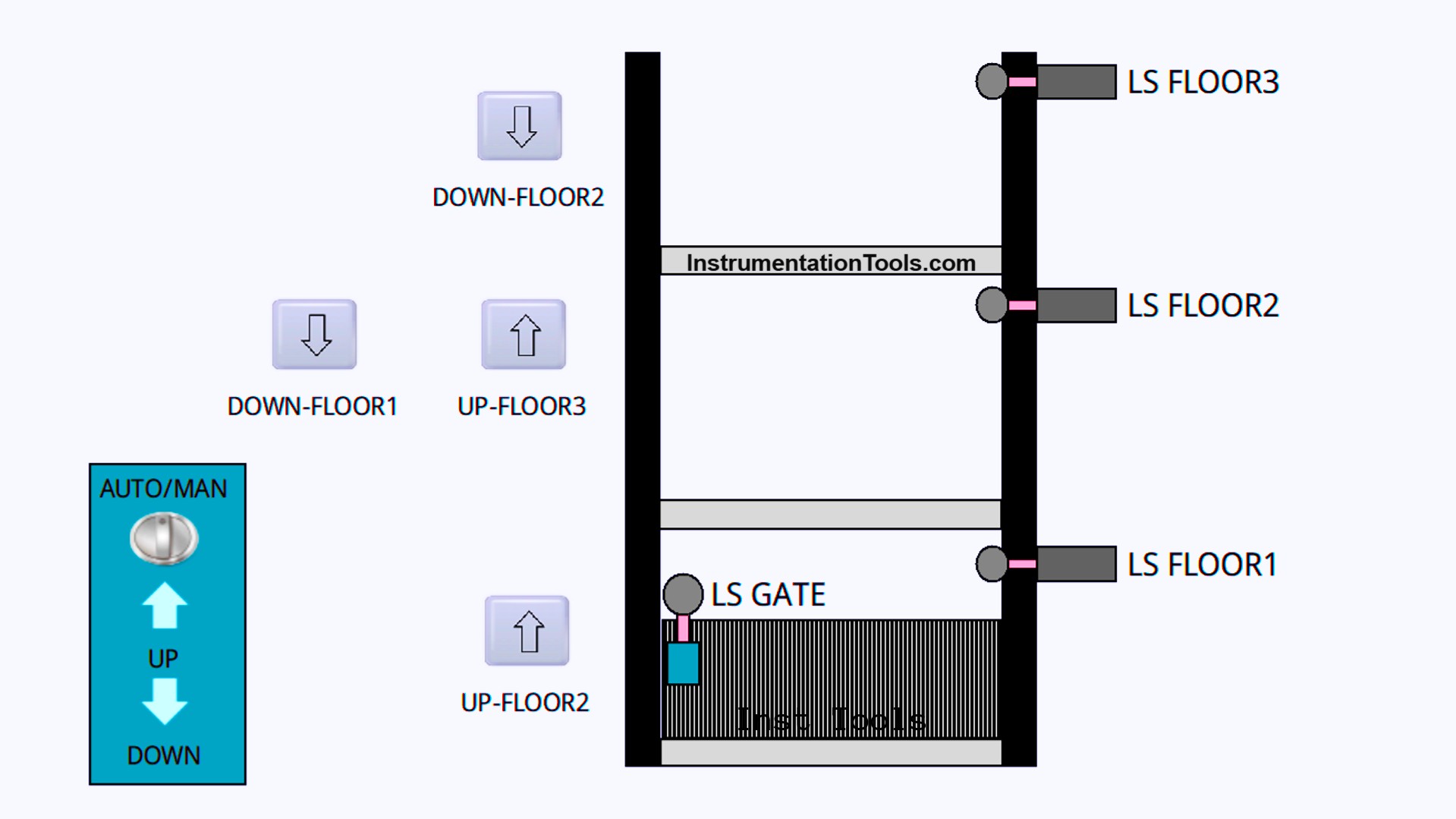
Elevator System with Safety Features
Program Inputs and Outputs
| S.No. | Comment | Input (I) | Output(Q) | Memory Bit |
| 1 | PB_START | I0.0 | ||
| 2 | PB_STOP | I0.1 | ||
| 3 | AUTO/MANUAL | I0.2 | ||
| 4 | PB_UP_MANUAL | I0.3 | ||
| 5 | PB_DOWN_MANUAL | I0.4 | ||
| 6 | LS_GATE | I0.5 | ||
| 7 | UP_FLOOR2 | I0.6 | ||
| 8 | LS_FLOOR1 | I0.7 | ||
| 9 | LS_FLOOR2 | I1.0 | ||
| 10 | UP_FLOOR3 | I1.1 | ||
| 11 | LS_FLOOR3 | I1.2 | ||
| 12 | DOWN_FLOOR1 | I1.3 | ||
| 13 | DOWN_FLOOR2 | I1.4 | ||
| 14 | OUT_UP | Q0.0 | ||
| 15 | OUT_DOWN | Q0.1 | ||
| 16 | FLOOR1_TO_2 | Q0.2 | ||
| 17 | FLOOR2_TO_3 | Q0.3 | ||
| 18 | FLOOR2_TO_1 | Q0.4 | ||
| 19 | FLOOR3_TO_2 | Q0.5 | ||
| 20 | SYSTEM_ON | M0.0 |
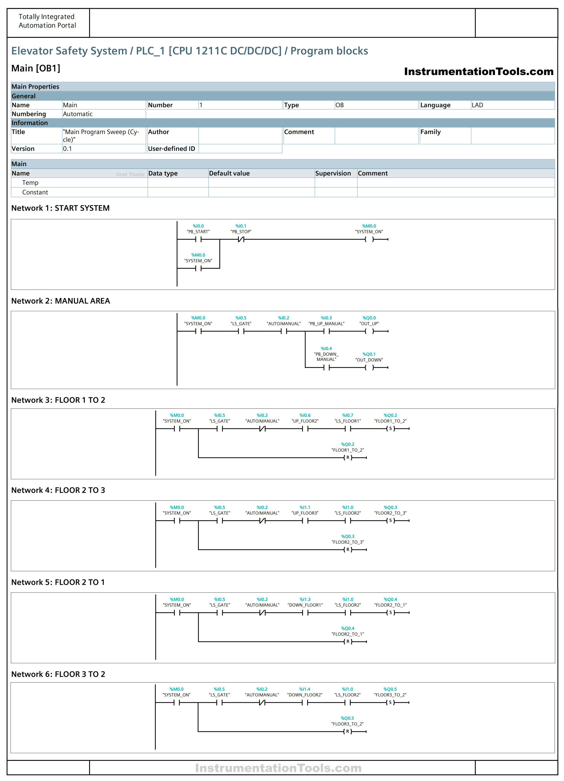
Siemens TIA Portal Logic
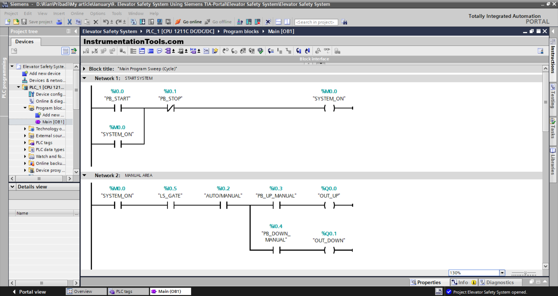
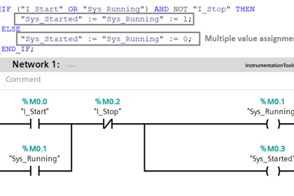
NETWORK 1 (START SYSTEM)
In this Network, when the PB_START (I0.0) button is Pressed, the memory bit SYSTEM_ON(M0.0)will be in the HIGH state. Because it uses the Latching Instruction, even though the PB_START (I0.0) button has been Released, the memory bit SYSTEM_ON(M0.0) will remain in the HIGH state.
If the PB_STOP (I0.1) button is Pressed, the memory bit SYSTEM_ON(M0.0) will be in the LOW state.
NETWORK 2 (MANUAL AREA)
In this Network, when the NO contact of the memory bit SYSTEM_ON(M0.0), the Limit Switch LS_GATE (I0.5), and the Selector Switch AUTO/MANUAL (I0.2) are in the HIGH state, and the PB_UP_MANUAL (I0.3) button Pressed, the output OUT_UP(Q0.0) will be ON.
When the NO contact of the memory bit SYSTEM_ON (M0.0), Limit Switch LS_GATE (I0.5), and Selector Switch AUTO/MANUAL (I0.2) are in the HIGH state, and the PB_DOWN_MANUAL (I0.4) button is Pressed, the output OUT_DOWN (Q0.1) will be ON.
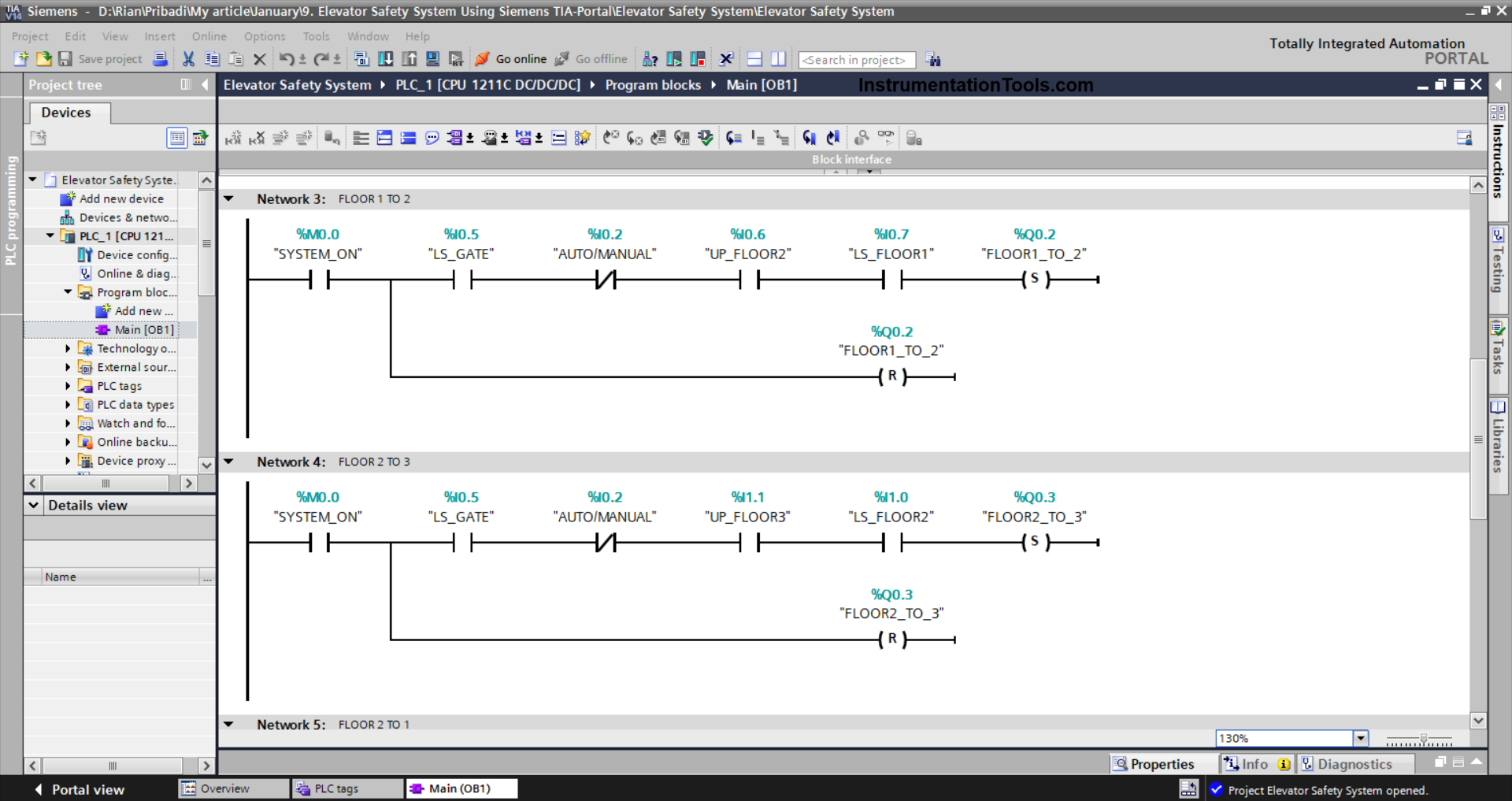
NETWORK 3 (FLOOR 1 to 2)
In this Network, the output FLOOR1_TO_2 (Q0.2) will be ON if the NO contact of the memory bit SYSTEM_ON (M0.0), Limit Switch LS_GATE (I0.5), and LS_FLOOR1 (I0.7) are in the HIGH state, and the UP_FLOOR2 (I0.6) button is Pressed.
Because it uses the SET Output Instruction, even though the UP_FLOOR2 (I0.6) button has been Released and the Limit Switch LS_FLOOR1(I0.7) is in the LOW state, the FLOOR1_TO_2(Q0.2) output state will remain in the ON state.
If the NO contact of the Limit Switch LS_FLOOR2 (I1.0) is in the HIGH state, then the output FLOOR1_TO_2 (Q0.2) will be OFF. Because it uses the RESET Output Instruction.
NETWORK 4 (FLOOR 2 to 3)
In this Network, the output FLOOR2_TO_3 (Q0.3) will be ON when the NO contact of the memory bit SYSTEM_ON (M0.0), Limit Switch LS_GATE (I0.5), and LS_FLOOR2 (I1.0) are in the HIGH state, and the UP_FLOOR3 (I1.1) button is Pressed.
Because it uses the SET Output Instruction, even though the UP_FLOOR3 (I1.1) button has been Released and the Limit Switch LS_FLOOR2 (I1.0) is in the LOW state, the FLOOR2_TO_3 (Q0.3) output state will remain in the ON state.
If the NO contact of the Limit Switch LS_FLOOR3 (I1.2) is in the HIGH state, then the output FLOOR2_TO_3 (Q0.3) will be OFF. Because it uses the RESET Output Instruction.
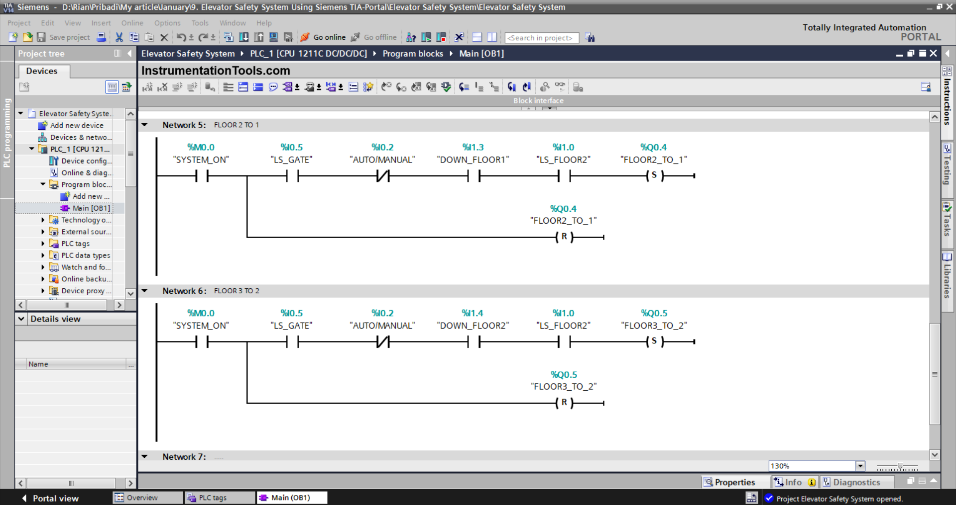
NETWORK 5 (FLOOR 2 to 1)
In this Network, the output FLOOR2_TO_1 (Q0.4) will be ON when the NO contact of the memory bit SYSTEM_ON (M0.0), the Limit Switch LS_GATE (I0.5), and LS_FLOOR2 (I1.0) are in the HIGH state, and the DOWN_FLOOR1 (I1.3) button is Pressed.
Because it uses the SET Output Instruction, even though the DOWN_FLOOR1 (I1.3) button has been Released and the Limit Switch LS_FLOOR2 (I1.0) is in the LOW state, the FLOOR2_TO_1 (Q0.4) output state will remain in the ON state.
If the NO contact of the Limit Switch LS_FLOOR1 (I0.7) is in the HIGH state, then the output FLOOR2_TO_1 (Q0.4) will be OFF. Because it uses the RESET Output Instruction.
NETWORK 6 (FLOOR 3 to 2)
In this Network, the output FLOOR3_TO_2 (Q0.5) will be ON when the NO contact of the memory bit SYSTEM_ON (M0.0), the Limit Switch LS_GATE (I0.5), and LS_FLOOR2 (I1.0) are in the HIGH state, and the DOWN_FLOOR2 (I1.4) button is Pressed.
Because it uses the SET Output Instruction, even though the DOWN_FLOOR2 (I1.4) button has been Released and the Limit Switch LS_FLOOR3 (I1.2) is in the LOW state, the FLOOR3_TO_2 (Q0.5) output state will remain in the ON state.
If the NO contact of the Limit Switch LS_FLOOR2 (I1.0) is in the HIGH state, then the output FLOOR3_TO_2 (Q0.5) will be OFF. Because it uses the RESET Output Instruction.
Read Next:
- Sequential Control of 3 Lights with Reset
- PLC Bottle’s Capping with Rotating Mechanism
- How to Configure IP Address in Rockwell PLC?
- PLC Interlock Logic with First Input Priority
- Complex Car Parking Logic in LS Electric PLC