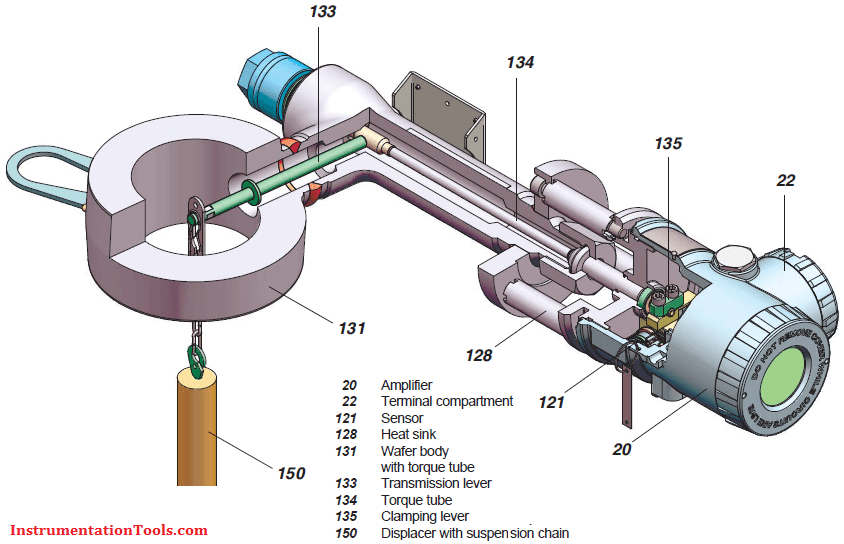
The buoyancy force of the displacer is transferred via transmission lever and torque tube to operating rod of the sensor, where it acts on free end of sensor element.Four thin film metal strain gauge elements are sputtered onto sensor element, which change their resistance in the ratio of the tensile or pressure tension. These four thin film metal strain gauge elements are connected as a Wheatstone full bridge supplied from amplifier.
The voltage at the diagonal bridge section which is proportional to the effective weight is fed to the electronic amplifier as an input signal. This voltage is converted via the electronic amplifier into the 4 to 20 mA or digital two-wire output signal. The amplifier is supplied by the signal current circuit in two wire mode.
CALIBRATION:
CALCULATING WEIGHT FORCES: For LRV & URV of Displacer Level Transmitter
Displacer length = measuring range
Displacer length > measuring range (without elevation)
Displacer length > measuring range (with elevation)
Downlaod Displacer Level Transmitter Formula
Measuring span
The transmitter is designed for a buoyancy force measuring span of minimum force to maximum force in N.
Weight force
The maximum weight of the displacer FG max for level measurements. For density or interface measurements, the displacer must be dimensioned so that after deducting FA of the lighter process media, the remaining force F0 does not exceed FG max.
Determining displacer diameters
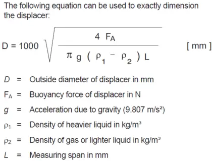
For optimum use of the transmitter, the displacer should be dimensioned so that the greatest possible buoyancy force is generated over the measuring range. On the other hand, the maximum possible diameter of the displacer must be taken into consideration. In the above graph the displacer diameter can easily be estimated dependent on the measuring span and the buoyancy force.
Measuring principle
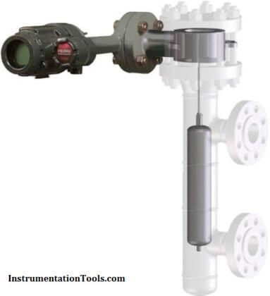
Any body immersed into a liquid is subject to buoyancy force which depends on the liquid density. This is exploited to determine liquid level, density and interface level by suspending a displacer with constant cylindric shape into a liquid. Changes in buoyancy forces are proportional to liquid level changes and are converted to a measuring signal. The displacer is fully immersed for density and interface level detection.
Also Read: Zero Suppression & Zero Elevation




Thanks so much
Thank You for the information Sir,i really like the blog you have posted,really meaningful.
valuable information for different types of instrumentation, thank you in advance.
What is calibration procedure of bubblers type level transmitter