Inst ToolsInst ToolsInst Tools
  • Courses
  • Automation
    • PLC
    • Control System
    • Safety System
    • Communication
    • Fire & Gas System
  • Instrumentation
    • Design
    • Pressure
    • Temperature
    • Flow
    • Level
    • Vibration
    • Analyzer
    • Control Valve
    • Switch
    • Calibration
    • Erection & Commissioning
  • Interview
    • Instrumentation
    • Electrical
    • Electronics
    • Practical
  • Q&A
    • Instrumentation
    • Control System
    • Electrical
    • Electronics
    • Analog Electronics
    • Digital Electronics
    • Power Electronics
    • Microprocessor
  • Request
Search
  • Books
  • Software
  • Projects
  • Process
  • Tools
  • Basics
  • Formula
  • Power Plant
  • Root Cause Analysis
  • Electrical Basics
  • Animation
  • Standards
  • 4-20 mA Course
  • Siemens PLC Course
Reading: Displacer Interface Level Measurement
Share
Font ResizerAa
Inst ToolsInst Tools
Font ResizerAa
  • Courses
  • Design
  • PLC
  • Interview
  • Control System
Search
  • Courses
  • Automation
    • PLC
    • Control System
    • Safety System
    • Communication
    • Fire & Gas System
  • Instrumentation
    • Design
    • Pressure
    • Temperature
    • Flow
    • Level
    • Vibration
    • Analyzer
    • Control Valve
    • Switch
    • Calibration
    • Erection & Commissioning
  • Interview
    • Instrumentation
    • Electrical
    • Electronics
    • Practical
  • Q&A
    • Instrumentation
    • Control System
    • Electrical
    • Electronics
    • Analog Electronics
    • Digital Electronics
    • Power Electronics
    • Microprocessor
  • Request
Follow US
All rights reserved. Reproduction in whole or in part without written permission is prohibited.
Inst Tools > Blog > Level Measurement > Displacer Interface Level Measurement

Displacer Interface Level Measurement

Last updated: August 8, 2019 4:41 pm
Editorial Staff
Level Measurement
1 Comment
Share
4 Min Read
SHARE

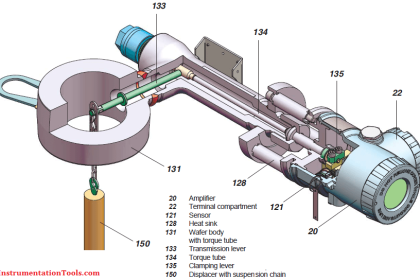
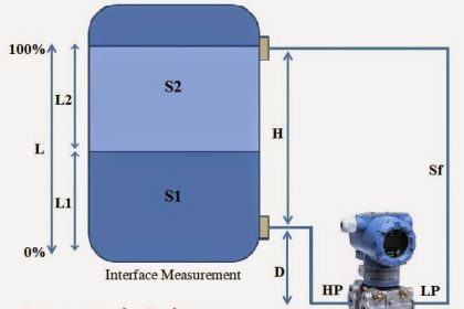
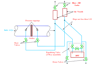
Displacer level instruments may be used to measure liquid-liquid interfaces just the same as hydrostatic pressure instruments. One important requirement is that the displacer always be fully submerged (“flooded”).

If this rule is violated, the instrument will not be able to discriminate between a low (total) liquid level and a low interface level. This criterion is analogous to the use of compensated-leg differential pressure instruments to measure liquid-liquid interface levels:

in order for the instrument to solely respond to changes in interface level and not be “fooled” by changes in total liquid level, both process connection points must be submerged.

If the displacer instrument has its own “cage,” it is important that both pipes connecting the cage to the process vessel (sometimes called “nozzles”) be submerged.

This ensures the liquid interface inside the cage matches the interface inside the vessel. If the upper nozzle ever goes dry, the same problem can happen with a caged displacer instrument as with a “sight glass” level gauge.

Calculating buoyant force on a displacer element due to a combination of two liquids is not as difficult as it may sound. Archimedes’ Principle still holds: that buoyant force is equal to the weight of the fluid(s) displaced.

All we need to do is calculate the combined weights and volumes of the displaced liquids to calculate buoyant force.

For a single liquid, buoyant force is equal to the weight density of that liquid (γ) multiplied by the volume displaced (V ):

Fbuoyant = γV

For a two-liquid interface, the buoyant force is equal to the sum of the two liquid weights displaced, each liquid weight term being equal to the weight density of that liquid multiplied by the displaced volume of that liquid:

Fbuoyant = γ1V1 + γ2V2

Assuming a displacer of constant cross-sectional area throughout its length, the volume for each liquid’s displacement is simply equal to the same area (πr2) multiplied by the length of the displacer submerged in that liquid:

Displacer interface level measurement

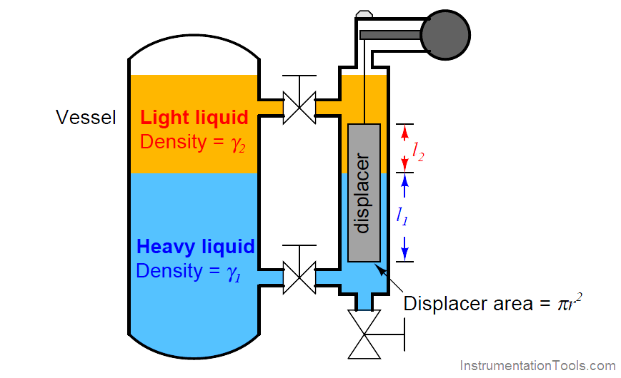
Fbuoyant = γ1πr2l1 + γ2πr2l2

Since the area (πr2) is common to both buoyancy terms in this equation, we may factor it out for simplicity’s sake:

Fbuoyant = πr2(γ1l1 + γ2l2)

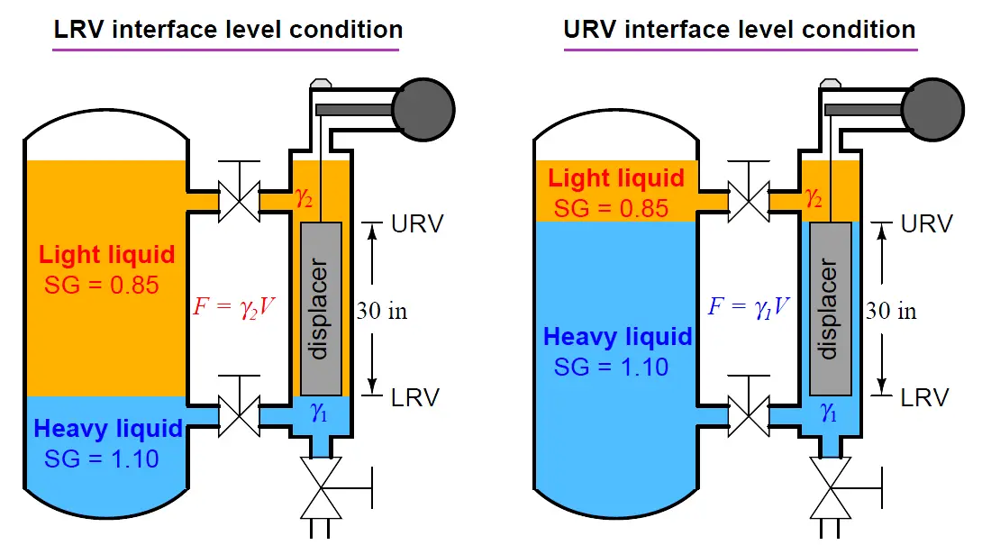
Determining the calibration points of a displacer-type level instrument for interface applications is relatively easy if the LRV and URV conditions are examined as a pair of “thought experiments” just as we did with hydrostatic interface level measurement.

First, we imagine what the displacer’s condition would “look like” with the interface at the lower range value, then we imagine a different scenario with the interface at the upper range value.

Sketching illustrations of each scenario is recommended for clarity.

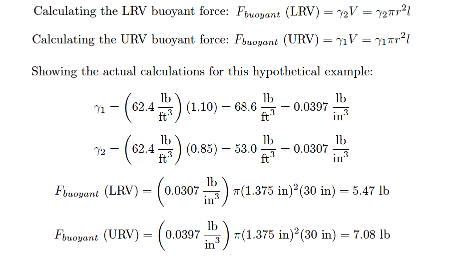
Suppose we have a displacer instrument measuring the interface level between two liquids having specific gravities of 0.850 and 1.10, with a displacer length of 30 inches and a displacer diameter of 2.75 inches (radius = 1.375 inches).

Let us further suppose the LRV in this case is where the interface is at the displacer’s bottom and the URV is where the interface is at the displacer’s top.

The placement of the LRV and URV interface levels at the extreme ends of the displacer’s length simplifies our LRV and URV calculations, as the LRV “thought experiment” will simply be the displacer completely submerged in light liquid and the URV “thought experiment” will simply be the displacer completely submerged in heavy liquid.

Displacer interface level measurement Calibration

Displacer interface level measurement Calculations

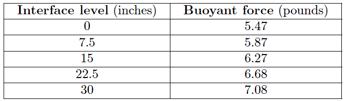
The buoyancy for any measurement percentage between the LRV (0%) and URV (100%) may be calculated by interpolation:

buoyancy for any measurement percentage

 Credits : Tony R. Kuphaldt – Creative Commons Attribution 4.0 License

Don't Miss Our Updates
Be the first to get exclusive content straight to your email.
We promise not to spam you. You can unsubscribe at any time.
Invalid email address
You've successfully subscribed !

Continue Reading

Closed Tank Remote Seal Capillary type DP Transmitter
Displacer Level Transmitter Dry Calibration with Weights
Calibration of Displacer Level Transmitter
Capacitive Level Measurement
Open Tank Level Measurement using DP Transmitter
Micro-impulse Level Transmitter Principle
Share This Article
Facebook Whatsapp Whatsapp LinkedIn Copy Link
Share
1 Comment
  • Victor Toma says:
    December 1, 2017 at 9:51 am

    As long as you don’t use SI in your presentations, this site will remain of limited use, professionalism and importance ( ….. and it is what a pity! …)

    Reply

Leave a Reply Cancel reply

Your email address will not be published. Required fields are marked *

Stay Connected

128.3kFollowersLike
69.1kFollowersFollow
210kSubscribersSubscribe
38kFollowersFollow

Categories

Explore More

Differential Pressure Level Transmitter Errors
How to do Interface Level Calculation using DP Transmitter ?
Ultrasonic Level Transmitter Principle, Limitations, Calibration and configuration
DP Level Transmitter Auto Calibration
Radar and Ultrasonic Level Transmitter Practical Problems Troubleshooting
Rotary Level Switch Working principle Animation
Level Calculation with Remote Seals
Displacer Level Transmitter Working Principle

Keep Learning

Closed tank DP Level Transmitter with wet leg elevation zero remote mount Calibration

Closed tank DP Level Transmitter with wet leg elevation zero remote mount Calibration

Closed Tank - Dry Reference Leg

Basics of Level Measurement

torque tube displacement level transmitter

Level Troll working principle

Types of Industrial Level Sensors

Types of Industrial Level Sensors

Questions on Level Switches

Questions on Level Switches

Boiler-Drum-Level-transmitter-calibration

Boiler Drum Level Transmitter Calibration

Tilt Level Switch Working Animation

Density Measurement using Remote Seal Transmitters

Remote Seal Differential Pressure Transmitters Principle

Learn More

Losses of Transformer

Phosphate Dozing System

Phosphate Dozing System Problems

gauge’s bourdon tube

Pressure Gauges : Remote and Chemical Seals

Turbine to Gearbox Alignment Drifts Caused Pump Transfers Problems

RCA Related to Trip Throttle Valve (TTV)

How Weigh Feeder Works

How Weigh Feeder Works ?

Electrical Machines Questions and Answers

Induction Machines Multiple Choice Questions

Single-acting Cylinder OR operation (PLC and Sensors)

Single-acting Cylinder OR Logic Operation (PLC and Sensors)

Read Temperature in PLC

PLC Program to Read Temperature in PLC

Menu

  • About
  • Privacy Policy
  • Copyright

Quick Links

  • Learn PLC
  • Helping Hand
  • Part Time Job

YouTube Subscribe

Follow US
All rights reserved. Reproduction in whole or in part without written permission is prohibited.
Welcome Back!

Sign in to your account

Username or Email Address
Password

Lost your password?