Resistance Temperature Detectors (RTDs), are sensors used to measure temperature. Many RTD elements consist of a length of fine wire wrapped around a ceramic or glass core but other constructions are also used.
The RTD wire is a pure material, typically platinum, nickel, or copper.
The material has an accurate resistance/temperature relationship which is used to provide an indication of temperature. As RTD elements are fragile, they are often housed in protective probes.
")
The following are the main disadvantages of Resistance Temperature Detectors are :
Self Heating
Heat energy is generated while applying current to excite the RTD element in order to measure its signal.
The self-heating that occurs will drive error in temperature measurement. Because the RTD changes its resistance in response to temperature, the most practical way to measure it is to pass a current through it and measure the resulting voltage drop.
Unfortunately, this excitation current passing through the element resistance raises the element temperature as it attempts to dissipate this electrical energy via heat, adding error to our temperature measurement.
The way to combat the positive shift driven by self heating is to increase thermal contact with the material we are sensing, and/or reduce the excitation current.
The self-heating of an RTD sensor is most often expressed in mW/°C, which refers to the power required to raise the internal element temperature 1°C. Thus, the higher this figure, the lower the self-heating will be.
For example, assume that 2mA of excitation current is used to drive a 100Ω platinum RTD at 100°C. This produces a sensor resistance of 138.5Ω. Its self-heating specification is 50mW/°C in water moving at 1m/second.
Thus, the amount of heat generated by this configuration is 1000mW/W * I2*R = 1000 * (0.002A)2 *138.5Ω = 0.55mW.
This results in a self-heating error of only (0.55mW)/(50mW/°C)=0.01°C.
It is important to note that the effective self-heating of an element depends strongly on the medium in which it is immersed.
For example, an RTD can self heat 100x higher in still air than in the moving water to which this specification applied.
Because we measure an RTDs resistance by drawing current through it, the I2R power dissipated by the RTD causes self-heating of the element.
Self-heating will change the RTD resistance and drive increased error in the measurement.
The negative effect of self-heating can be minimized by supplying lower excitation current.
Some instruments will use RTD excitation currents down to 0.1mA to minimize this error.
In the above example, this would reduce self-heating to ~0.001mW/50mW/°C=0.00003°C, an insignificant amount, even in still air.
The magnitude of this error is inversely proportional to the capacity of the sensor element to dissipate the heat. This is a product of its materials, construction, and its environment.
Small bodied RTD elements will have higher self-heating effects as they have smaller surface areas over which to dissipate the heat.
Perhaps the worst case would be a thin-film RTD which would typically have a high thermal resistance and corresponding little surface area to dissipate the heat.
Typically, a dissipation constant is provided in RTD sensor specifications. This number relates the power required to raise the RTD temperature by one degree of temperature.
Thus, a 25mW/°C dissipation constant shows that if I2R power losses in the RTD equal 25 mW, then the RTD will be heated by 1 °C.
The dissipation constant is usually specified under two conditions: free air and a well-stirred oil bath. This is because of the difference in capacity of the medium to carry heat away from the device.
The self-heating temperature rise can be found from the power dissipated by the RTD and the dissipation constant via the following:
ΔT = P/ PD
where ΔT = temperature rise because of self-heating in °C; P = power dissipated in the RTD from the circuit in W; and PD = dissipation constant of the RTD in W/°C.
Summary :
Self-heating errors are caused by the inability of the RTD element to dissipate the heat generated by the required power applied via the measuring current.
The ASTM Standard requires the error to be a maximum of 1 °C when 33 mW is applied in 25 °C water, IEC requires a maximum error of 0.05 °C in 25 °C water when the maximum operating current is applied.
These test methods are good laboratory comparison methods For PRTs installed with proper immersion in a process, the operating current is 1 mA or less, so the power (I2R) for a 100 Ω PRT is also small (0.02–0.39 mW).
Lager errors can occur in sensors with resistances in the 500–1000 Ω range, or when the process exhibits poor heat transfer conditions such as still air or low-pressure gases.
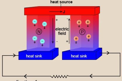
Thermal EMF or Seebeck or Thermoelectric Effect
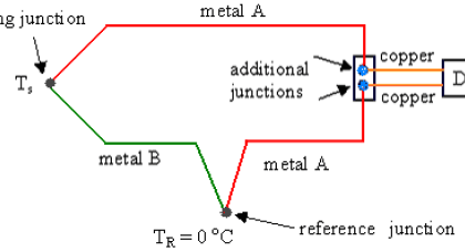
Perhaps you thought that the Seebeck effect only applied to thermocouples? But similar to thermocouples, platinum RTDs are also constructed using two different metals–the platinum RTD element and the copper of the lead wires.
For some applications, these connections in the sensor loop can generate Seebeck voltages that can counter the IR drops produced in the resistance element and throw off the reading slightly.
For example, if a temperature gradient is allowed to develop along the sensing element, then a thermoelectric voltage of approximately 7uV/°C can develop as a result of the junctions between the platinum sensor element and the copper lead wire.
For most applications, this small counter-emf will not be a significant source of error, but can lead to problems in very high precision measurement systems operating at low excitation currents (perhaps done to minimize self-heating errors)—conditions usually only encountered in laboratory measurements.
The material and construction of an RTD make it a relatively bulky element, and this also makes it difficult to use the RTD to measure temperature at a single point of contact.
However, an RTD provides an excellent means of measuring the average temperature over a surface, and it does this by spreading the resistance wire contact over a surface area.
But if this surface contact also spreads over some distance, such that the lead wire connections at each end of the element are displaced too far apart, then this can lead to Seebeck error, which is a byproduct of the thermal gradient that occurs between the two Platinum-Copper connections to the lead wires.
These errors can be prevented by using appropriate lead wire and careful sensor positioning relative to the lead wires.
In a nutshell, a different lead material like copper can produce a T/C junction where it connects to the platinum element, and then another T/C junction at the other end.
If the two junctions are at different temperatures, then a thermoelectric emf will develop that can throw off the IR measurement of the RTD element.
The algebraic sum of the thermoelectric emf in a circuit composed of any number of dissimilar materials is zero, if all of the junctions are maintained at a uniform temperature.
So you only have two remedies to combat this effect: either use a lead-wire of the same material as the element (not practical, as this would be very expensive for a platinum element with long leads), or simply keep the temperatures at each junction the same (i.e along the element), or nearly the same, which would result in negligible net emf contribution to your voltage measurement.
Summary :
Thermal EMF errors are also known as the thermocouple effect. This error is caused by various wire compositions, wire connections in homogeneity of materials, and temperature gradients within the PRT (RTD).
The ASTM and IEC Standards offer guidelines at high sensing currents—although when an EMF influence exists, it will have a greater effect at lower currents near the standard operating current.
This error occurs primarily in direct current systems. To minimize thermal EMF errors, select a PRT with a low specified EMF.
Also, using alternating current circuitry and appropriately selected transmitters can eliminate EMF influences.
Response Time or Time Response
The time constant of an RTD refers to the speed with which its element changes resistance in response to a change in contact temperature.
A rapid time constant helps to reduce error in a measurement system that encounters rapid changes in temperature.
When we consider the construction of an RTD, we can infer that response time will have a strong dependence on the mass of the sensor element and its insulating structure, as well as the heat transfer capability to the material being sensed.
This directly affects the rate at which heat transfers from the outer sensing surface to the core sensing element.
Comparatively, because an RTD measures temperature over a larger area, rather than small point of contact like the thermocouple, and because the RTD sensing element must be insulated, it has a much slower response time than a thermocouple.
Likewise, an RTD probe in a thermowell will react more slowly than the same sensor immersed directly into a fluid.
A sensor in a solidly bonded internal assembly would respond twice as fast as one with a single loose interface in the same assembly.
A surface RTD will respond more quickly to a surface temperature change.
The response time for a given sensor is typically defined as the time it takes the sensor to reach 63% of its final value at thermal equilibrium in response to a step-change in contact temperature.
These times are typically expressed as measured in water flowing at 1m/sec (3ft/sec), and/or in air flowing at 3m/sec (10ft/sec).
Although less common, sometimes the response time will refer to the time interval for the Platinum RTD to reach 90% of its final value (as opposed to 63%).
Be sure to make note of this distinction when making comparisons between sensor types.
Summary :
A time response-related error can be produced during temperature transients if the PRT (RTD) cannot respond to the change in temperature fast enough.
During steady-state or near-steady-state operation, this error is zero. ASTM and IEC do not define this error, although there is a test method to characterize a PRTs’ response time for comparison purposes.
When it is important to monitor transient conditions, this error can be minimized by selecting a sensor with a faster lab-tested response time and assessing the related rate of change to the process to best match the sensors’ time response performance.
Article Source : Acromag


thank’s