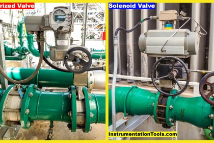
2/2 Direct Lift Diaphragm Normally Closed Solenoid Valve

To open:
when the valve receives an electrical signal, a magnetic field is formed which attracts the plunger covering the main orifice to lift off, causing system pressure to drop.
As system pressure on the top of the diaphragm is reduced, full system pressure on the other side of the diaphragm acts to lift the diaphragm away from the main orifice, which allows media to flow through the valve.
Since the bleed orifice is dimensionally smaller than the pilot orifice, the system pressure cannot rebuild on the top of the diaphragm as long as the pilot orifice remains open. When the system pressure is 0 PSI, the valve also can be operated.
![]()
To close:
when the valve is de-energized, it releases its hold on the plunger. Then the plunger forced by the spring drops and covers the main orifice.
The system pressure builds up on the top of the diaphragm through the bleed orifice, forcing the diaphragm down until it covers the main orifice and stops media flow through the valve. When the system pressure is 0 PSI, the valve still can be operated.
2/2 Direct Lift Diaphragm Normally Open Solenoid Valve

To close:
when the valve is energized, it attracts the plunger. Then the plunger covers the main orifice.
The system pressure builds up on the top of the diaphragm/piston through the bleed orifice, forcing the diaphragm/piston down until it covers the main orifice and stops media flow through the valve. When the system pressure is 0 PSI, the valve also can be operated.

To open:
when the valve is de-energized, it releases its hold on the plunger. The plunger uncovers the pilot orifice causing system pressure holding the diaphragm/piston closed to drop.
As system pressure on the top of the diaphragm/piston is reduced, full system pressure on the opposite side of the diaphragm/piston acts to lift the diaphragm/piston away from the main orifice, which allows the full media flow through the valve. When the system pressure is 0 PSI, the valve also can be operated.