Inst ToolsInst ToolsInst Tools
  • Ask
  • Courses
  • Videos
  • Q & A
    • Interview
      • Instrumentation
      • Electronics
      • Electrical
      • Practical Questions
    • MCQ
      • Instrumentation MCQ
      • Electrical MCQ
      • Electronics MCQ
      • Control Systems MCQ
      • Analog Electronics MCQ
      • Digital Electronics MCQ
      • Power Electronics MCQ
      • Microprocessor MCQ
      • Multiple Choice Questions
  • EE
    • Electronics
      • Electronics Q & A
      • Electronic Basics
      • Electronic Devices & Circuits
      • Electronics Animation
      • Digital Electronics
    • Electrical
      • Electrical Basics
      • Electrical Q & A
      • Power Electronics
      • Electrical Machines
      • Electrical Animation
      • Power Systems
      • Switchgear & Protection
      • Transmission & Distribution
  • Measure
    • Control Valves
    • Calibration
    • Temperature
    • Pressure
    • Flow
    • Level
    • Analyzers
    • Switches
    • Vibration
    • Solenoid Valve
  • Control
    • PLC Tutorials
    • Control Systems
    • Safety Instrumented System (SIS)
    • Communication
    • Fire & Gas System
  • More
    • Design
    • Tools
    • Animation
    • Basics
    • Formulas
    • Standards
    • TextBooks
    • Common
    • Software
    • Excel Tools
    • Erection & Commissioning
    • Process Fundamentals
    • Videos
    • Books
Search
All rights reserved. Reproduction in whole or in part without written permission is prohibited.
Reading: DC Motor Torque
Share
Notification Show More
Font ResizerAa
Inst ToolsInst Tools
Font ResizerAa
  • Courses
  • PLC Tutorials
  • Control Systems
Search
  • Ask
  • Courses
  • Videos
  • Q & A
    • Interview
    • MCQ
  • EE
    • Electronics
    • Electrical
  • Measure
    • Control Valves
    • Calibration
    • Temperature
    • Pressure
    • Flow
    • Level
    • Analyzers
    • Switches
    • Vibration
    • Solenoid Valve
  • Control
    • PLC Tutorials
    • Control Systems
    • Safety Instrumented System (SIS)
    • Communication
    • Fire & Gas System
  • More
    • Design
    • Tools
    • Animation
    • Basics
    • Formulas
    • Standards
    • TextBooks
    • Common
    • Software
    • Excel Tools
    • Erection & Commissioning
    • Process Fundamentals
    • Videos
    • Books
Follow US
All rights reserved. Reproduction in whole or in part without written permission is prohibited.
Inst Tools > Blog > Electrical Theory > DC Motor Torque

DC Motor Torque

Last updated: July 28, 2018 3:15 pm
Editorial Staff
Electrical Theory
No Comments
Share
3 Min Read
SHARE

Torque is defined as that force which tends to produce and maintain rotation. The function of torque in a DC motor is to provide the mechanical output or drive the piece of equipment that the DC motor is attached to.

When a voltage is applied to a motor, current will flow through the field winding, establishing a magnetic field. Current will also flow through the armature winding, from the negative brush to the positive brush as shown in Figure 5.

Armature Current in a DC Motor

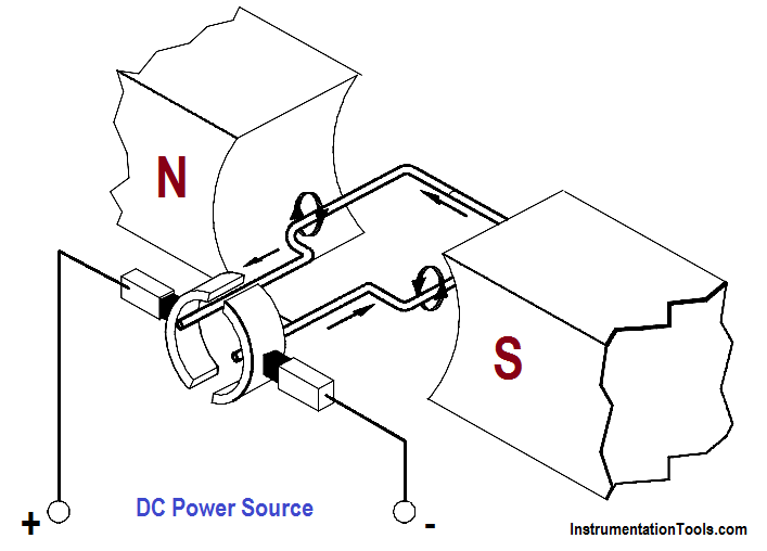
Figure 5 : Armature Current in a Basic DC Motor

Since the armature is a current carrying conductor in a magnetic field, the conductor has a force exerted on it, tending to move it at right angles to that field. Using the left-hand rule for current carrying conductors, you will see that the magnetic field on one side is strengthened at the bottom, while it is weakened on the other side.

Using the right-hand rule for motors, we can see that there is a force exerted on the armature which tends to turn the armature in the counter-clockwise direction. The sum of the forces, in pounds, multiplied by the radius of the armature, in feet, is equal to the torque developed by the motor in pound-feet.

It is evident from Figure 5 that if the armature current were reversed, but the field were the same, torque would be developed in the opposite direction. Likewise, if the field polarity were reversed and the armature remained the same, torque would also be developed in the opposite direction.

The force that is developed on a conductor of a motor armature is due to the combined action of the magnetic fields. The force developed is directly proportional to the strength of the main field flux and the strength of the field around the armature conductor. As we know, the field strength around each armature conductor depends on the amount of current flowing through the armature conductor. Therefore, the torque which is developed by the motor can be determined using Equation.

T = K Φ Ia

where

T  = torque, lb-ft
K  = a constant depending on physical size of motor
Φ = field flux, number of lines of force per pole
Ia = armature current

Don't Miss Our Updates
Be the first to get exclusive content straight to your email.
We promise not to spam you. You can unsubscribe at any time.
Invalid email address
You've successfully subscribed !
Batteries
Discharge and Charging of Lead-Acid Battery
Batteries Theory
Synchronous Motors
Electrical Symbols
Share This Article
Facebook Whatsapp Whatsapp LinkedIn Copy Link
Share
Leave a Comment

Leave a Reply Cancel reply

Your email address will not be published. Required fields are marked *

Stay Connected

128.3kFollowersLike
69.1kFollowersFollow
208kSubscribersSubscribe
38kFollowersFollow

Categories

Recent Comments

  • Guifty Shimica on Top Non-PLC Certification Courses for Automation Professionals
  • Guifty Shimica on Top Non-PLC Certification Courses for Automation Professionals
  • MIHARITSOA Aina Sitraka on Top Non-PLC Certification Courses for Automation Professionals
  • Vaishnavi on Free Instrumentation Course for Trainee Engineers

Related Articles

Compounded DC Generator

Parallel AC Generators

Calculate Power in Parallel RC Circuit

Calculate Power in Parallel RC Circuit

Transformer voltage and turns ratio

Transformer Voltage Ratio

Single Line Diagram

Single Line Diagram

Electrical Wiring Terminology

Electrical Wiring Terminology

Unbalanced 3 Phase Loads

Unbalanced 3 Phase Loads

circuit breaker principle

What is a circuit breaker ?

Parallel Circuit

Parallel Circuit

More Articles

Wrong Orifice Installation

How Not to Install an Instrument and Wrong Practices

CNC Milling versus CNC Turning

CNC Milling versus CNC Turning – Which is the Best Option?

Battery Interview QuBattery Interview Question and Answersestion and Answers

Battery Interview Question and Answers

Function Block Diagram - Studio 5000 Logix Designer

Define the Order of Execution in Functional Block Diagram of Studio 5000

Pressure Gauge Accessories

Pressure Gauge Accessories

Valve Basics, Sizing, and Actuators Books

Valve Basics, Sizing, and Actuators Books

Ladder Logic Example of Two Motors

Ladder Logic Example of Two Motors Interlinked with another Motor

Annubar flow principle

Different Types of Flow Elements

Follow US
All rights reserved. Reproduction in whole or in part without written permission is prohibited.
Welcome Back!

Sign in to your account

Username or Email Address
Password

Lost your password?