Inst ToolsInst ToolsInst Tools
  • Courses
  • Automation
    • PLC
    • Control System
    • Safety System
    • Communication
    • Fire & Gas System
  • Instrumentation
    • Design
    • Pressure
    • Temperature
    • Flow
    • Level
    • Vibration
    • Analyzer
    • Control Valve
    • Switch
    • Calibration
    • Erection & Commissioning
  • Interview
    • Instrumentation
    • Electrical
    • Electronics
    • Practical
  • Q&A
    • Instrumentation
    • Control System
    • Electrical
    • Electronics
    • Analog Electronics
    • Digital Electronics
    • Power Electronics
    • Microprocessor
  • Request
Search
  • Books
  • Software
  • Projects
  • Process
  • Tools
  • Basics
  • Formula
  • Power Plant
  • Root Cause Analysis
  • Electrical Basics
  • Animation
  • Standards
  • 4-20 mA Course
  • Siemens PLC Course
Reading: DC Generator
Share
Font ResizerAa
Inst ToolsInst Tools
Font ResizerAa
  • Courses
  • Design
  • PLC
  • Interview
  • Control System
Search
  • Courses
  • Automation
    • PLC
    • Control System
    • Safety System
    • Communication
    • Fire & Gas System
  • Instrumentation
    • Design
    • Pressure
    • Temperature
    • Flow
    • Level
    • Vibration
    • Analyzer
    • Control Valve
    • Switch
    • Calibration
    • Erection & Commissioning
  • Interview
    • Instrumentation
    • Electrical
    • Electronics
    • Practical
  • Q&A
    • Instrumentation
    • Control System
    • Electrical
    • Electronics
    • Analog Electronics
    • Digital Electronics
    • Power Electronics
    • Microprocessor
  • Request
Follow US
All rights reserved. Reproduction in whole or in part without written permission is prohibited.
Inst Tools > Blog > Electrical Theory > DC Generator

DC Generator

Last updated: July 22, 2018 11:04 pm
Editorial Staff
Electrical Theory
No Comments
Share
1 Min Read
SHARE

A simple DC generator consists of an armature coil with a single turn of wire. The armature coil cuts across the magnetic field to produce a voltage output. As long as a complete path is present, current will flow through the circuit in the direction shown by the arrows in Figure 2. In this coil position, commutator segment 1 contacts with brush 1, while commutator segment 2 is in contact with brush 2.

Rotating the armature one-half turn in the clockwise direction causes the contacts between the commutator segments to be reversed. Now segment 1 is contacted by brush 2, and segment 2 is in contact with brush 1.

DC Generator

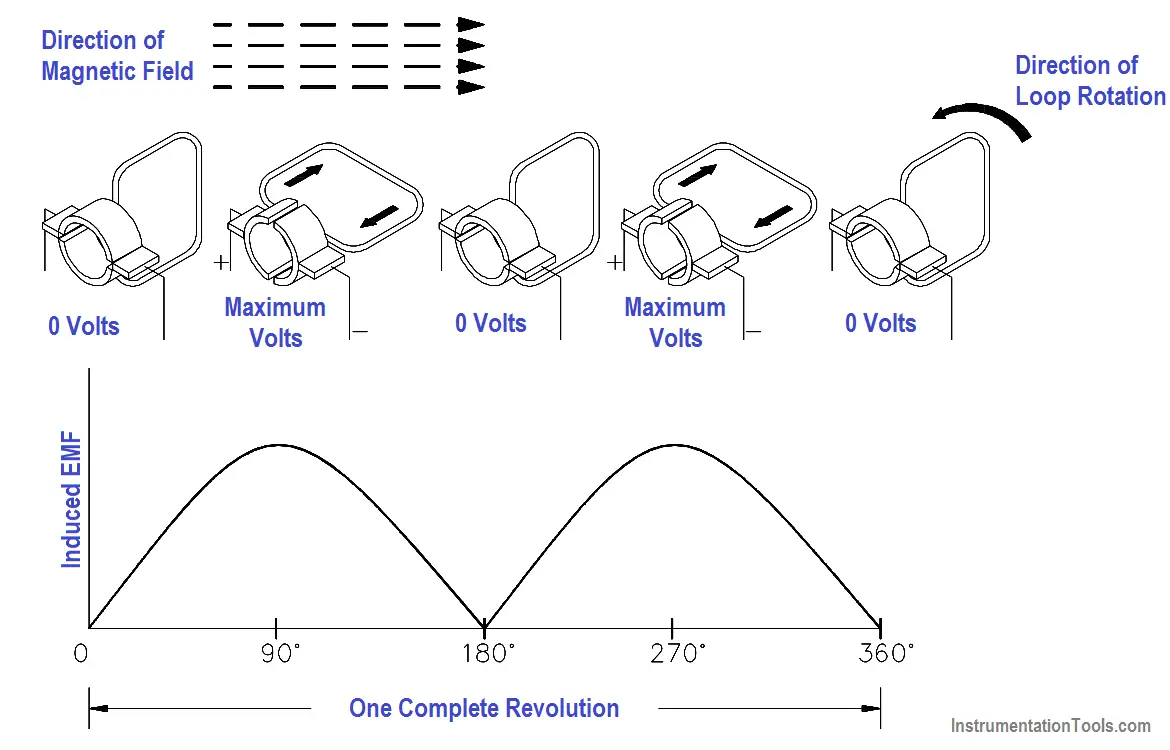
Figure 2 Basic DC Generator

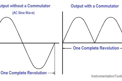
Due to this commutator action, that side of the armature coil which is in contact with either of the brushes is always cutting the magnetic field in the same direction. Brushes 1 and 2 have a constant polarity, and pulsating DC is delivered to the load circuit.

Don't Miss Our Updates
Be the first to get exclusive content straight to your email.
We promise not to spam you. You can unsubscribe at any time.
Invalid email address
You've successfully subscribed !

Continue Reading

Resistivity
Impedance in RLC Circuits
Electrical Wiring Terminology
Capacitance
Power Triangle
Discharge and Charging of Lead-Acid Battery
Share This Article
Facebook Whatsapp Whatsapp LinkedIn Copy Link
Share
Leave a Comment

Leave a Reply Cancel reply

Your email address will not be published. Required fields are marked *

Stay Connected

128.3kFollowersLike
69.1kFollowersFollow
210kSubscribersSubscribe
38kFollowersFollow

Categories

Explore More

DC Generator Internal Losses
Ground Detector Principle
Power in Balanced 3 Phase Loads
AC Induction Motor Slip
Types of Batteries
DC Generator Theory
Battery Terminology
AC Motor Theory

Keep Learning

Three Phase Transformer Connections

Three Phase Transformer Connections

Inductors in parallel

Series and Parallel Inductors

Power Triangle

Apparent Power, True Power, Reactive Power & Total Power

Electric Short Circuit

Electric Circuit : Open & Short Circuits

LVR Motor Controller Operation

Low Voltage Protection (LVP) and Low Voltage Release (LVR)

Wattmeter Principle

Wattmeter

Power Factor Meter Principle

Power Factor Meter Principle

Resistor Y and Delta Network Calculation

Y and Delta Resistor Network Calculations

Learn More

Control Systems Multiple Choice Questions

Instrumentation Cables Questions Answers

Instrumentation Cables Questions & Answers

pneumatic piston actuator

Working Principle of Pneumatic Actuators

Power Electronics Objective Questions

Current Source Inverters Objective Questions

Motor Library in Studio 5000 PLC

Create User-Defined Data Types and Function Blocks in Studio 5000

Difference between PVC, XLPE, and Insulated Cables

Difference between PVC, XLPE, and Insulated Cables

Pipeline Pig Detector

What are Non-Intrusive Pig Signallers or Pig Detectors?

Marshalling Panel

What is Marshalling Cabinet?

Menu

  • About
  • Privacy Policy
  • Copyright

Quick Links

  • Learn PLC
  • Helping Hand
  • Part Time Job

YouTube Subscribe

Follow US
All rights reserved. Reproduction in whole or in part without written permission is prohibited.
Welcome Back!

Sign in to your account

Username or Email Address
Password

Lost your password?