Inst ToolsInst ToolsInst Tools
  • Ask
  • Courses
  • Videos
  • Q & A
    • Interview
      • Instrumentation
      • Electronics
      • Electrical
      • Practical Questions
    • MCQ
      • Instrumentation MCQ
      • Electrical MCQ
      • Electronics MCQ
      • Control Systems MCQ
      • Analog Electronics MCQ
      • Digital Electronics MCQ
      • Power Electronics MCQ
      • Microprocessor MCQ
      • Multiple Choice Questions
  • EE
    • Electronics
      • Electronics Q & A
      • Electronic Basics
      • Electronic Devices & Circuits
      • Electronics Animation
      • Digital Electronics
    • Electrical
      • Electrical Basics
      • Electrical Q & A
      • Power Electronics
      • Electrical Machines
      • Electrical Animation
      • Power Systems
      • Switchgear & Protection
      • Transmission & Distribution
  • Measure
    • Control Valves
    • Calibration
    • Temperature
    • Pressure
    • Flow
    • Level
    • Analyzers
    • Switches
    • Vibration
    • Solenoid Valve
  • Control
    • PLC Tutorials
    • Control Systems
    • Safety Instrumented System (SIS)
    • Communication
    • Fire & Gas System
  • More
    • Design
    • Tools
    • Animation
    • Basics
    • Formulas
    • Standards
    • TextBooks
    • Common
    • Software
    • Excel Tools
    • Erection & Commissioning
    • Process Fundamentals
    • Videos
    • Books
Search
All rights reserved. Reproduction in whole or in part without written permission is prohibited.
Reading: How CPU Execute Program in Siemens PLC?
Share
Notification Show More
Font ResizerAa
Inst ToolsInst Tools
Font ResizerAa
  • Courses
  • PLC Tutorials
  • Control Systems
Search
  • Ask
  • Courses
  • Videos
  • Q & A
    • Interview
    • MCQ
  • EE
    • Electronics
    • Electrical
  • Measure
    • Control Valves
    • Calibration
    • Temperature
    • Pressure
    • Flow
    • Level
    • Analyzers
    • Switches
    • Vibration
    • Solenoid Valve
  • Control
    • PLC Tutorials
    • Control Systems
    • Safety Instrumented System (SIS)
    • Communication
    • Fire & Gas System
  • More
    • Design
    • Tools
    • Animation
    • Basics
    • Formulas
    • Standards
    • TextBooks
    • Common
    • Software
    • Excel Tools
    • Erection & Commissioning
    • Process Fundamentals
    • Videos
    • Books
Follow US
All rights reserved. Reproduction in whole or in part without written permission is prohibited.
Inst Tools > Blog > PLC Tutorials > How CPU Execute Program in Siemens PLC?

How CPU Execute Program in Siemens PLC?

Learn about how CPU execute a program in the Siemens PLC, it reads the inputs from the input module then values are saved to PII (Process Image Input).

Last updated: March 4, 2021 11:22 am
Editorial Staff
PLC Tutorials
1 Comment
Share
4 Min Read
SHARE

In this article, we will learn about the execution of the program in the PLC.

Many people want to learn PLC programming directly without knowing what happens around it.

Before jumping into the programming, you must learn the basics of the PLC, how the program works, the flow of the program, and during execution how it uses memory, etc.

How CPU Execute Program in Siemens PLC?

How CPU Execute Program in Siemens PLC?

Here we are going to learn about how CPU executes a program in the Siemens PLC, although execution will remain the same in every PLC, in Siemens PLC it will take a little extra for an execution.

Normally in every PLC execution takes place like reading the Input, evaluate the logic and writing the output,

However, in the Siemens PLC, it reads the inputs from the input module then values are saved to PII (Process Image Input).

PII is a small memory part that resides in the CPU to store the status of the inputs coming from the input module.

Now you may have a question that why to save the value to PII? It’s because by saving input to PII it reduces the amount of the scan cycle. Which is helpful in a case where you have a large number of I/Os are available.

So, every time instead of looking back to the input module, CPU only looks at PII to make the execution of the program fast enough.

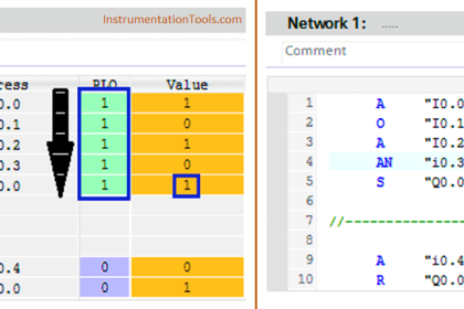
After PII, CPU then starts to process the program. It checks the status of the Inputs and based on their condition (ON/OFF) it processes the logic.

First, it goes for the first network and sees whether the input is active or not, if not then it moves to the next network and checks the input status. This process will last until the end of the program.

So, in the processing of the program flow goes from the top to bottom and left to right.

Now, for example in the processing part CPU sees that some of the inputs are true, what it does that it saves that output to the PIQ (Process Image Output).

After saving the output to the PIQ, it then goes to the output module to energize output resides in the field.

After this process CPU goes to the first step and repeats the same step again n again.

This is how PLC executes the logic in Siemens PLC.

Now, you might have one more question that is this works for both the analog and digital signal? The answer is NO.

Only for the digital inputs and outputs CPU looks at PII and PIQ, but in case of the analog signal, it takes a value directly from the module.

As the analog signal takes a value from the module itself, to recognize the analog inputs and outputs it uses P before writing any addresses like PIW100, PQW100, etc.

Still, you have a question? Then ask me through the below comment section.

Author: Suhel Patel

If you liked this article, then please subscribe to our YouTube Channel for PLC and SCADA video tutorials.

You can also follow us on Facebook and Twitter to receive daily updates.

Read Next:

  • Allen Bradley Architecture
  • Allen Bradley Powerflex VFD
  • Motor Push button Logic
  • Motor Forward and Reverse
  • Solenoid and PLC Wiring
Don't Miss Our Updates
Be the first to get exclusive content straight to your email.
We promise not to spam you. You can unsubscribe at any time.
Invalid email address
You've successfully subscribed !
Micro PLC Hardware Configuration
PLC Math instructions
Power Supply Sizing for Industrial Automation Systems
PLC Program for Bank Counter Application
PLC Example with Switches
Share This Article
Facebook Whatsapp Whatsapp LinkedIn Copy Link
Share
1 Comment
  • saif says:
    November 5, 2023 at 6:43 pm

    still i wonder if the output pin are energised sequentially same as the networks or they are all energised at one time after the sequential scan of networks is done ?

    Reply

Leave a Reply Cancel reply

Your email address will not be published. Required fields are marked *

Stay Connected

128.3kFollowersLike
69.1kFollowersFollow
208kSubscribersSubscribe
38kFollowersFollow

Categories

Recent Comments

  • Guifty Shimica on Top Non-PLC Certification Courses for Automation Professionals
  • Guifty Shimica on Top Non-PLC Certification Courses for Automation Professionals
  • MIHARITSOA Aina Sitraka on Top Non-PLC Certification Courses for Automation Professionals
  • Vaishnavi on Free Instrumentation Course for Trainee Engineers

Related Articles

Difference between Signal Cables and Control Cables

Difference between Signal Cables and Control Cables

Water Treatment Plant SCADA

Typical HMI Screen Design for Water Treatment Plant

PLC Water Project

Smart Spray System using Wecon PLC

21 CFR in SCADA and HMI Systems

What is 21 CFR in SCADA and HMI Systems?

In this article, we will learn the difference between Machine Expert Basic and Machine Expert software in Schneider PLC.

Difference between Machine Expert Basic and Machine Expert – Schneider PLC

What is RS Linx - Types of Softwares in Rockwell Automation

What is RS Linx? Types of Software in Rockwell Automation

Conveyor and Puncher PLC Program

Toggle Switch & Sensor: Conveyor and Puncher PLC Program

PLC Programmer Salary and Future Career Scope

PLC Programmer Salary and Future Career Scope

More Articles

Types of Tripping Protection in MCCB

Types of Tripping Protection in MCCB

How to Test a Pressure Switch ?

How to Test a Pressure Switch ?

Purpose of End of Line (EOL) Resistor in Fire & Gas System ?

Why we use End of Line (EOL) Resistor in Fire and Gas System ?

Frequency Response MCQ

Bode Plots MCQ

Electric Motor Actuator Parts

Electric Motor Actuator Parts

Direct Acting Solenoid Valve

Top 5 Things for selecting a Solenoid Valve

Conveyor Speed Logic using Structured Text in PLC

Conveyor Speed Logic using Structured Text in PLC

Power Electronics Objective Questions

Power Electronics Diode Circuits Questions and Answers

Follow US
All rights reserved. Reproduction in whole or in part without written permission is prohibited.
Welcome Back!

Sign in to your account

Username or Email Address
Password

Lost your password?