Coriolis flowmeter design uses a U shaped tube that redirects the fluid flow back to the center of rotation.
The curved end of the flexible U-tube is forced to shake back and forth by an electromagnetic force coil (like the force coil on an audio speaker) while the tube ends anchor to a stationary manifold:
Coriolis Flow Meter
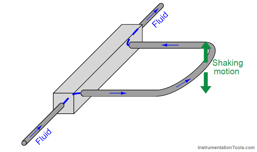
If fluid inside the tube is stagnant (no flow), the tube will simply vibrate back and forth with the applied force.
However, if fluid flows through the tube, the moving fluid molecules will experience acceleration as they travel from the anchored base to the tube’s rounded end, then experience deceleration as they travel back to the anchored base.
This continual acceleration and subsequent deceleration of new mass generates a Coriolis force altering the tube’s motion.
Construction
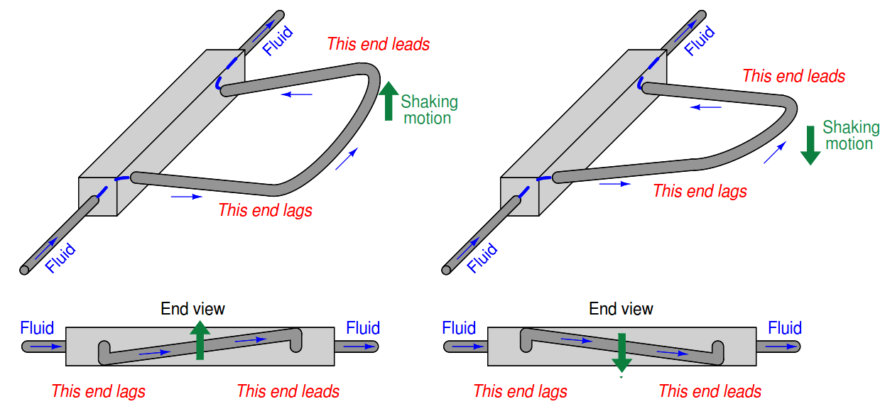
This Coriolis force causes the U-tube assembly to twist. The tube portion carrying fluid from the anchored base to the end tends to lag in motion because the fluid molecules in that section of the tube are being accelerated to a greater lateral velocity.
The tube portion carrying fluid from the end back to the anchored base tends to lead in motion because those molecules are being decelerated back to zero lateral velocity. As mass flow rate through the tube increases, so does the degree of twisting.
By monitoring the severity of this twisting motion, we may infer the mass flow rate of the fluid passing through the tube:
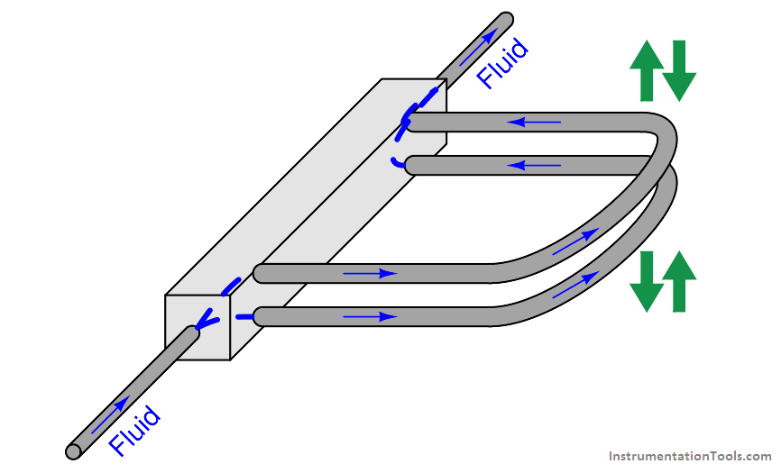
In order to reduce the amount of vibration generated by a Coriolis flowmeter, and more importantly to reduce the effect any external vibrations may have on the flowmeter, two identical Utubes are built next to each other and shaken in complementary fashion (always moving in opposite directions).
Tube twist is measured as relative motion from one tube to the next, not as motion between the tube and the stationary housing of the flowmeter.
This (ideally) eliminates the effect of any common-mode vibrations on the inferred flow measurement:
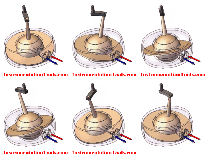
Viewed from the end, the complimentary shaking and twisting of the tubes looks like this:
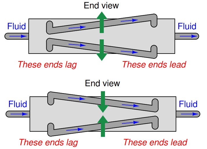
Great care is taken by the manufacturer to ensure the two tubes are as close to identical as possible: not only are their physical characteristics precisely matched, but the fluid flow is split very evenly between the tubes so their respective Coriolis forces should be identical in magnitude.
Rosemount Micro-Motion Flow Meter
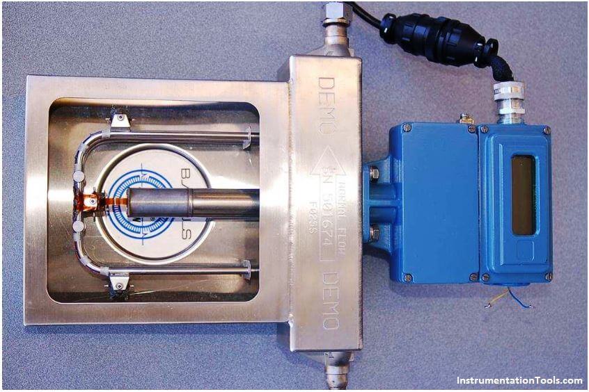
A photograph of a Rosemount (Micro-Motion) U-tube Coriolis flow meter demonstration unit shows the U-shaped tubes (one tube is directly above the other in this picture, so you cannot tell there are actually two U-tubes):
A closer inspection of this flow meter shows that there are actually two U-tubes, one positioned directly above the other, shaken in complementary directions by a common electromagnetic force coil:
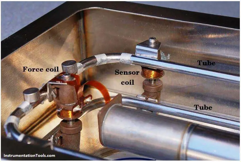
The force coil works on the same principle as an audio speaker: AC electric current passed through a wire coil generates an oscillating magnetic field, which acts against a permanent magnet’s field to produce an oscillating force.
In the case of an audio speaker, this force causes a lightweight cone to move, which then creates sound waves through the air. In the case of the Coriolis meter assembly, the force pushes and pulls between the two metal tubes, causing them to alternately separate and come together (shake in opposite directions).
Two magnetic displacement sensors monitor the relative motions of the tubes and transmit signals to an electronics module for digital processing.
One of those sensor coils may be seen in the previous photograph. Both the force coil and the sensor coil are nothing more than permanent magnets surrounded by movable copper wire coils.
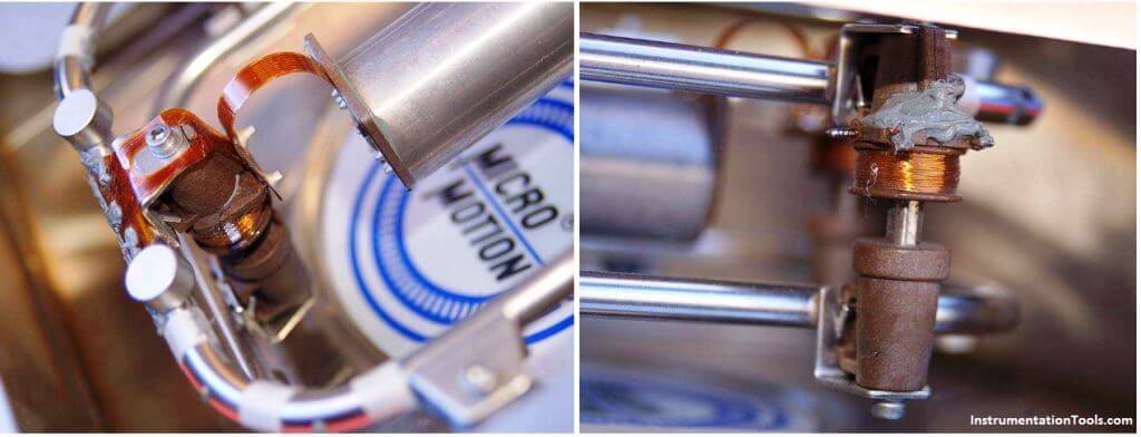
The main difference between the force coil and the sensor coil is that the force coil is powered by an AC electric current to impart a vibratory force to the tubes, whereas the sensor coils are both un-powered so they can detect tube motion by generating AC voltage signals to be sensed by the electronics module.
The force coil is shown in the left-hand photograph, while one of the two sensor coils appears in the right-hand photograph:
The two AC signals generated by the sensor coils provide data from which the electronics package may interpret fluid density and mass flow rate.
The frequency of the two coils’ signals is inversely related to fluid density, because a denser fluid will cause the tubes to have greater mass and therefore vibrate at a lower frequency (Note 1). The phase shift of the two coils’ signals is directly related to mass flow rate, because a greater mass flow rate will cause the tubes to twist to a greater degree, causing the sensors’ signals to shift further out of phase with each other.
Note 1 : The force coil is powered by an electronic amplifier circuit, which receives feedback from the sensor coils. Like any amplifier circuit given positive (regenerative) feedback, it will begin to oscillate at a frequency determined by the feedback network. In this case, the feedback “network” consists of the force coil, tubes, and sensor coils.
The tubes, having both resilience and mass, naturally possess their own resonant frequency. This mechanical resonance dominates the feedback characteristic of the amplifier loop, causing the amplifier circuit to oscillate at that same frequency.
Advances in sensor technology and signal processing have allowed the construction of Coriolis flowmeters employing straighter tubes than the
U-tube unit previously illustrated and photographed. Straighter tubes are advantageous for reasons of reduced plugging potential and the ability to easily drain all liquids out of the flow meter when needed.
In straight-tube Coriolis flow meters, we still find the same general design of a force coil flanked by matching sensor coils measuring vibration frequency (for density measurement) and phase shift (for mass flow measurement).
If you liked this article, then please subscribe to our YouTube Channel for Instrumentation, Electrical, PLC, and SCADA video tutorials.
You can also follow us on Facebook and Twitter to receive daily updates.
Read Next:
- Magnetic Flow Meter Animation
- Flow Switch Animation
- Swirl Flow Meter Operation
- Ultrasonic Flow meter Factors
- What is a Restriction Orifice?
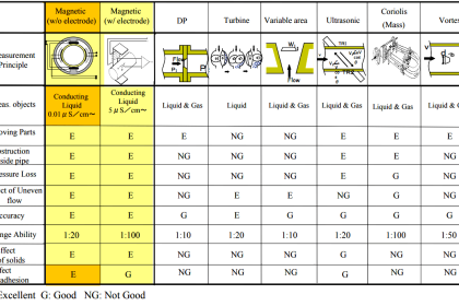



This depicts the early evolution of the coriolis meter (by the way, there is some question of whether “coriolis” is the correct interpretation of the phenomenon; see articles in the flow group on Linked in) which began life as a single tube and necessitated very rigid vibration free reference and hence the move to the use of two tubes.
The D Type and some others originally vibrated the tubes at mains frequency… 50Hz or 60Hz which was unfortunate in that this corresponds the the dominant pipe line transmitted pulsations and could also lead to cross talk between meters.
There was also claimed to be a weakness of this tube shape in that the welds where the tubes were joined leading to some failures. It is also a problem that in some applications problems could arise where, e.g. with high solids or viscous fluids, one tube could be partially blocked leading to unbalanced flows.
I don’t know but I would have to suspect that the twin tube solution might have been inspired by the Solartron twin tube vibrating elements densitometer.
None the less a very successful design but which Micro Motion was forced to address when competitors entered the market (leading to patent suits). Perhaps the two most notable were the Neptune M Dot which used and advanced “coat hanger” tube geometry which was fare more style tube geometry which was more flexible and without the weld stress. It also used resonant frequency to drive the tubes. This meant that the operating frequency was much higher and relatively immune to pipe born vibrations which, because of the higher freqencies and where such high frequency sources were in the pipework, the amplitude tended to diminish to below interference levels within a vary short distance of the source. The way Micro motion responded to this was to implement these ideas in a new generation of twin tube viscometer, the Elite. This may not have been better than the Neptune but matched it and because of their much larger installed base and client list made it possible to protect against any significant further share loss.
The other technology was more problematic. This was the Exac coriolis meter (Fisher Controls).
This meter used a single tube design consisting to a double spiral such that one section of the tube was vibratated against a subsequent section of the tube. This eliminated any possibility of low imbalance or the need for careful design of flow splitters. It also eliminated the problem of one tube blocking and unbalancing the flows. The geometry was also, probably, far more flexible and thus less energy required to generate sufficent signals at low flows. Many users considered this concept superior to the twin tube approach.
However, Rosemount, who owned Mirco Motion and Fisher Controls, the owners of Exac, engaged in an expensive patent battle which was resolved when Rosemount bought out Fisher and formed the Fisher-Rosemount group with Exac coming under the control of Rosemount.
After a while the Exac design was discontinued. A disappointment but a logical business decision given the far greater footprint in the market of the twin tube designs.
Over the years a number of other geometries emerged such as the twin straight tube designs which utilised small diameter twin parallel tubes, the small diameter to generate higher flow velocities necessary to give a good signal to noise ratios,
However one should not ignore the Solartron single straight tube design, the Massmaster.
This was (despite some claims to the contrary) the first single straight full bore mass flowmeter which was also IS approved two wire transmitter with smart amplifier option.The single straight tube was vibrated against nodal masses and the tube connected to the pipework through triple layer bellows which gave it immunity to temperature effects 9a concern for many designs). Sadly before it had a chance to complete its evolution Solartron cancelled this meter and though they are now part of Emerson (who took over the Fisher Rosemount group) the blame for this meter being cancelled lies with Solartron. I always considered this a poor decision as most meters have some teething problems when they first are introduced and there was nothing that time and R&D could not resolve. It also proved able to measure gas mass flow, by the way, and its density accuracy was of fiscal standards (Until the use of resonant frequency, Coriolis meters could only report the mass flow and not the density, another advantage of both the Exac and the M Dot but corrected in the Elite).
There are other geometries which could be employed such as a single straight tube massmeter which by having a short bore length and large bores would easily overcome one of the major problems with twin tube mass meters, that of pressure drop.
Oh, and in twin bent tube designs another issue is that of tube erosion due to the flow patterns passing through the bends and especially with high solids.
THis is an excellent technology and it has a great future.
A lot of effort has gone into two phase (liquid and Gas) but, and I may be well out of date here, this works up to about 10% GVF and depends on a more or less uniform dispersion of gas bubbles. Above this it seems that gas pockets could be encountered leading to imbalances, but I stand to be corrected on this.
I look forward to seeing further developments in coriolis measurements.