Inst ToolsInst ToolsInst Tools
  • Courses
  • Automation
    • PLC
    • Control System
    • Safety System
    • Communication
    • Fire & Gas System
  • Instrumentation
    • Design
    • Pressure
    • Temperature
    • Flow
    • Level
    • Vibration
    • Analyzer
    • Control Valve
    • Switch
    • Calibration
    • Erection & Commissioning
  • Interview
    • Instrumentation
    • Electrical
    • Electronics
    • Practical
  • Q&A
    • Instrumentation
    • Control System
    • Electrical
    • Electronics
    • Analog Electronics
    • Digital Electronics
    • Power Electronics
    • Microprocessor
  • Request
Search
  • Books
  • Software
  • Projects
  • Process
  • Tools
  • Basics
  • Formula
  • Power Plant
  • Root Cause Analysis
  • Electrical Basics
  • Animation
  • Standards
  • 4-20 mA Course
  • Siemens PLC Course
Reading: Conveyor Operation with a Backup Motor using PLC Ladder Diagram
Share
Font ResizerAa
Inst ToolsInst Tools
Font ResizerAa
  • Courses
  • Design
  • PLC
  • Interview
  • Control System
Search
  • Courses
  • Automation
    • PLC
    • Control System
    • Safety System
    • Communication
    • Fire & Gas System
  • Instrumentation
    • Design
    • Pressure
    • Temperature
    • Flow
    • Level
    • Vibration
    • Analyzer
    • Control Valve
    • Switch
    • Calibration
    • Erection & Commissioning
  • Interview
    • Instrumentation
    • Electrical
    • Electronics
    • Practical
  • Q&A
    • Instrumentation
    • Control System
    • Electrical
    • Electronics
    • Analog Electronics
    • Digital Electronics
    • Power Electronics
    • Microprocessor
  • Request
Follow US
All rights reserved. Reproduction in whole or in part without written permission is prohibited.
Inst Tools > Blog > PLC Tutorials > Conveyor Operation with a Backup Motor using PLC Ladder Diagram

Conveyor Operation with a Backup Motor using PLC Ladder Diagram

In this article, you will learn the conveyor operation using the main motor and backup motor with PLC ladder diagram logic.

Last updated: September 28, 2022 2:22 pm
Hussien Ghareb
PLC Tutorials
No Comments
Share
5 Min Read
SHARE

Continuity and reliability are essential advantages a plant or system can have. So, in this case, failures should be predicted and also you have to prepare a swift solution or actions for such a situation.

Contents
Explaining Conveyor OperationPLC Ladder Diagram using Siemens TIA Portal

Today we are going to have a simple common situation that is presented in most plants that contain some critical conveyors that cannot be stopped for any reason.

Explaining Conveyor Operation

Here we have a very simple conveyor that is a part of a whole system.

The main problem is if this conveyor stopped the whole factory and the system operation will stop, that means increasing system downtime, and by its role that would cost you a lot of money.

To avoid such a situation, we are using a backup motor for some critical conveyors in some plants, all we need a backup motor that is connected with the same motion axe of the conveyor motor. As shown in Fig. (1)

Conveyor Control with Main Motor and Backup Motor
Figure 1

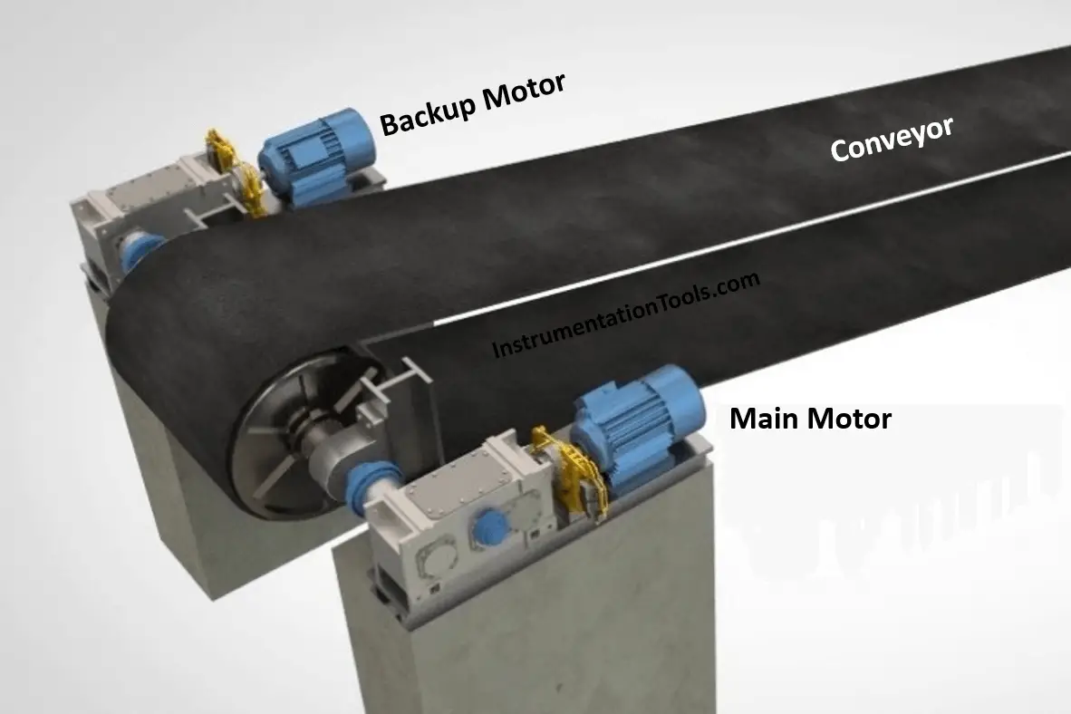
In case of failure of the main motor, the backup motor will work instead of it.

Register Siemens PLC Course: Click Here

PLC Ladder Diagram using Siemens TIA Portal

We discussed the PLC ladder logic networks designed in the Siemens Tia portal.

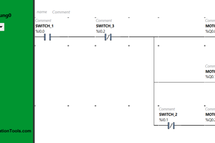
Network 1: Controlling the Main Motor

Here we have the first network that is shown in Fig. (2) as we can see by clicking on (I0.0) we can start the main motor.

PLC Controlling the Main Motor
Figure 2

Notice that (I0.2) is the stop push button and it is already NC.

Also, we have an electrical interlock from the backup motor presented in (NC from Q0.1). to prevent the two motors from working together.

If the motor stops the bit (M0.2) would indicate that and it will stop the order of running that is presented on the digital outputs of the PLC signals.

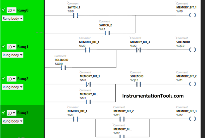
Network 2: Controlling the Backup Motor

Then we have the second network that is shown in Fig. (3) as we can see by clicking on (I0.1) we can start the main motor.

PLC Control Backup Motor
Figure 3

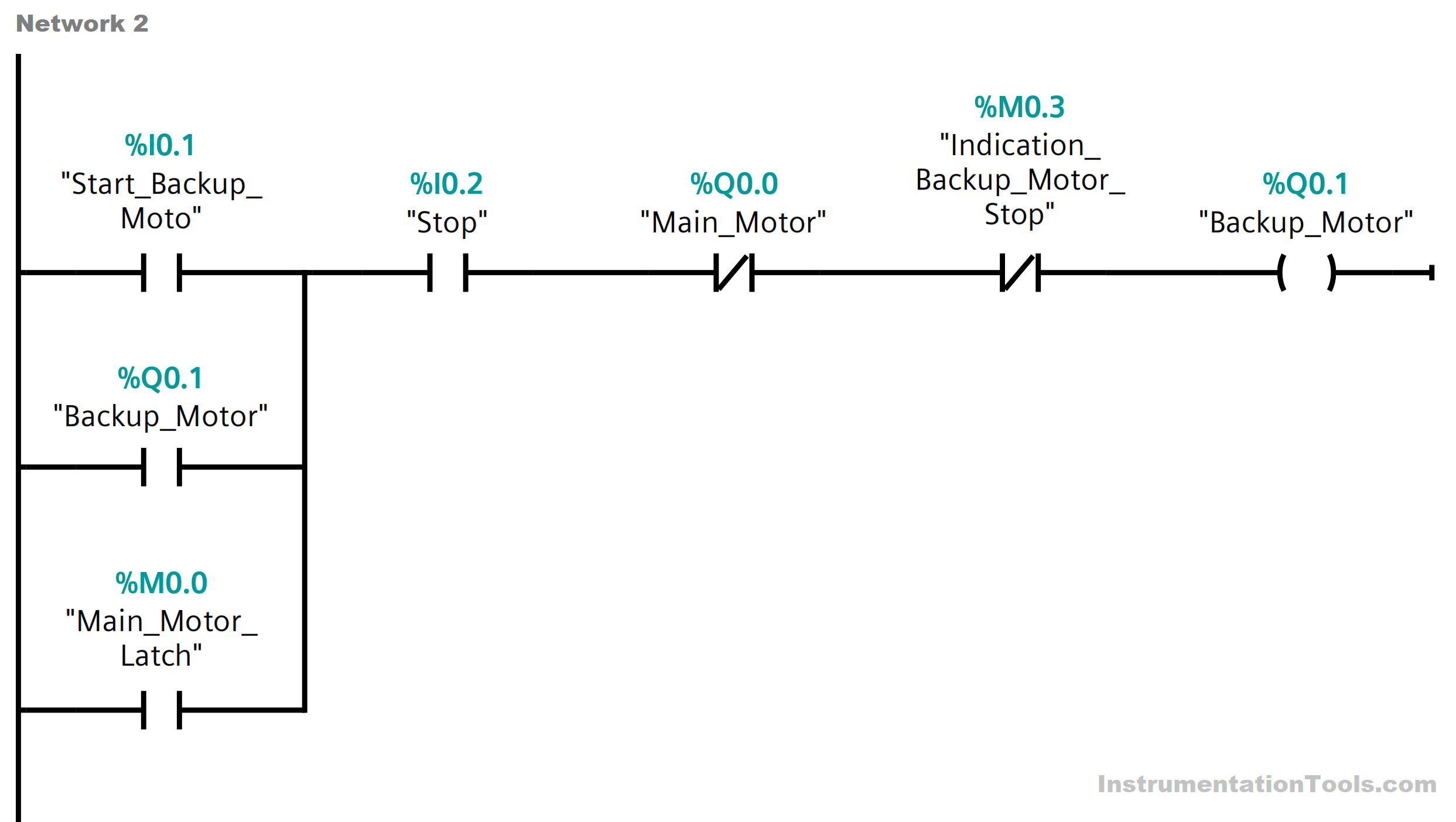
Beside the motor latch (Q0.1) we can see a bit (M0.0) that also can operate the backup motor in case of failure.

Also, we have an electrical interlock from the backup motor presented in (NC from Q0.1). to prevent the two motors from working together.

If the backup motor stops the bit (M0.3) would indicate that and it will stop the order of running that is presented on the digital outputs of the PLC signals.

Network 3: Main Motor Latch

For this network that is presented in Fig. (4) we can see that if any failure (Motor Stoppage) is indicated on the main motor by this bit (M0.2), the bit of (the main motor latch “M0.0”) will be energized.

Main Motor Latch in PLC
Figure 4

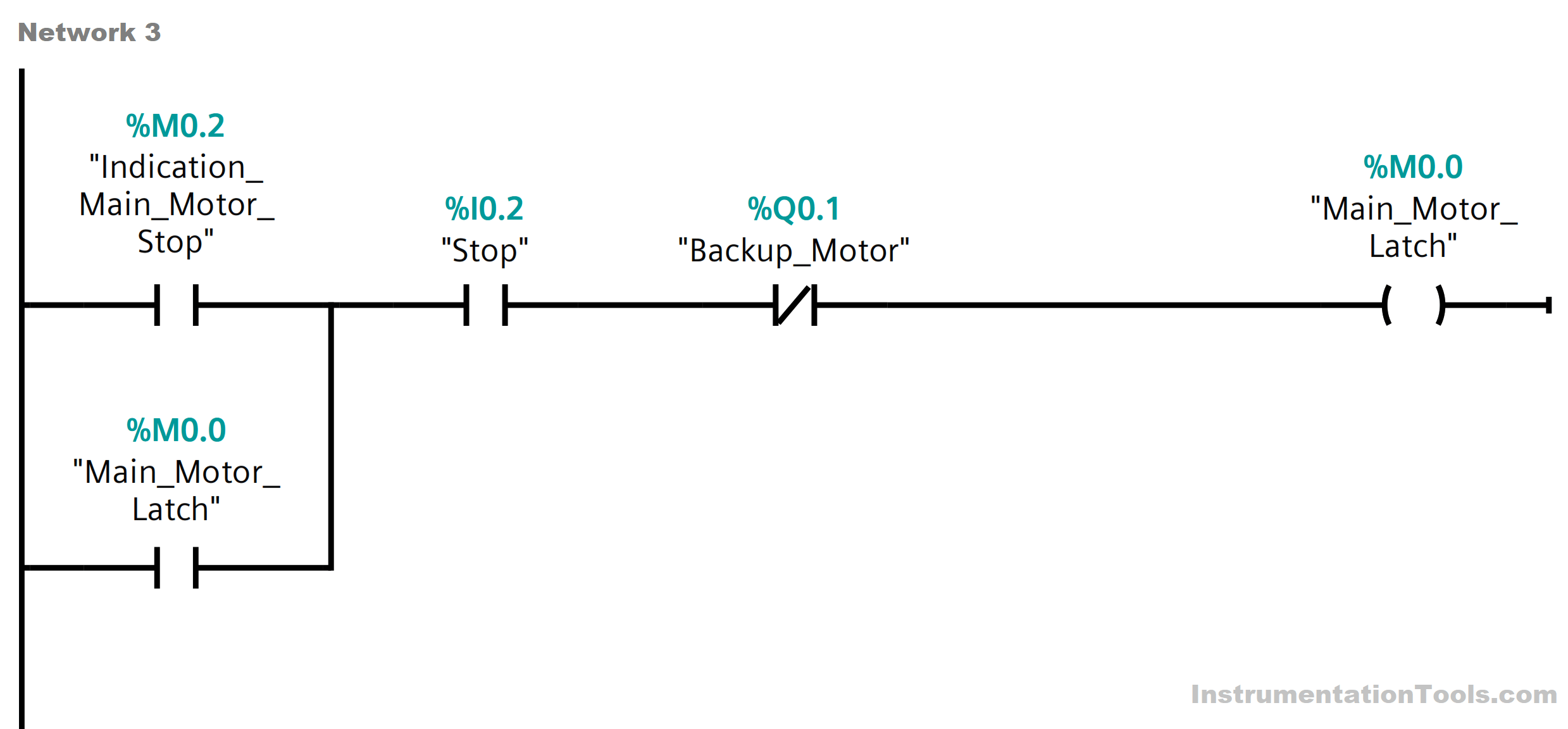
Then as you can see in Fig. (3) this bit will operate the backup motor then when the backup motor is on (by its role) it will de-energize the main motor latch (M0.0) again.

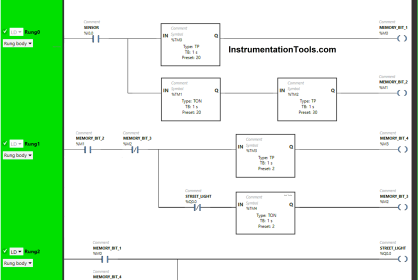
Network 4: Backup Motor Latch

Here we have the last network presented in Fig. (5) we can see that if any failure (Motor Stoppage) is indicated on the backup motor by this bit (M0.3), this bit (the backup motor latch “M0.1”) will be energized.

Conveyor Operation with a Backup Motor using Ladder Diagram
Figure 5

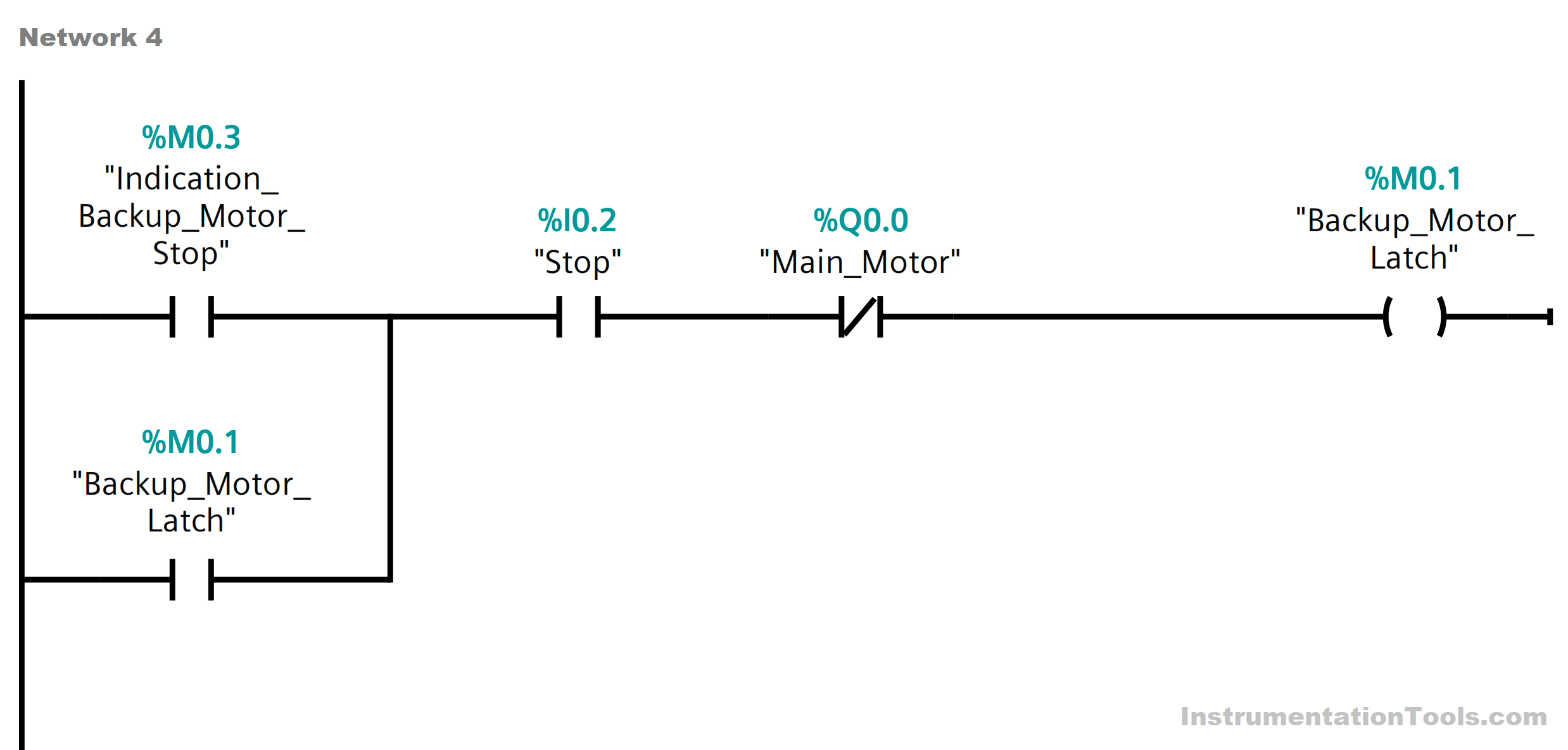
Then as you can see in Fig. (2) this bit will operate the main motor back again then when the main motor is on (by its role) it will de-energize the backup motor latch (M0.1) again.

If you liked this article, then please subscribe to our YouTube Channel for Instrumentation, Electrical, PLC, and SCADA video tutorials.

You can also follow us on Facebook and Twitter to receive daily updates.

Read Next:

  • Scan Cycle in SIEMENS PLC
  • Cloud-Based SCADA Projects
  • PLC-based Gas Detection System
  • Create New Project in Studio 5000
  • Rockwell Allen Bradley PLC Projects
Don't Miss Our Updates
Be the first to get exclusive content straight to your email.
We promise not to spam you. You can unsubscribe at any time.
Invalid email address
You've successfully subscribed !

Continue Reading

T Flip Flop PLC Ladder Diagram
Animation of Electromagnetic Relay
Top 5 Advantages of Human-Machine Interface (HMI)
Parts of PLC
SCADA Hardware and Software
Components of PLC
Share This Article
Facebook Whatsapp Whatsapp LinkedIn Copy Link
Share
Leave a Comment

Leave a Reply Cancel reply

Your email address will not be published. Required fields are marked *

Stay Connected

128.3kFollowersLike
69.1kFollowersFollow
210kSubscribersSubscribe
38kFollowersFollow

Categories

Explore More

How to Automatically Close Pop-up in FactoryTalk View Studio?
Parking Garage Indicator: PLC Automation System
Everything You Need to Know About PLC Battery
PLC Program for Alternate Output Circuit with Latched Function
What is Trace Function in Tia Portal?
Example PLC Program to Control a Pump based on Level Sensors
Static and Temp Variables in PLC
Which Connection is Best for PLC? – Sinking or Sourcing

Keep Learning

PC-Based Motion Controller

Various Types of Delta PLC used in Industrial Automation

Modbus in Industrial Networks

How Modbus is used in Industrial Networks?

PLC based Door Open and Closing System

PLC based Door Open and Closing System

Hardwired IO and Serial IO - Differences Explained

Hardwired I/O and Serial I/O – Differences Explained

PLC Programming Example with Pushbutton and Motor

PLC Programming Example with Pushbutton and Motor

Yokogawa DCS Tutorials - Configuration of Analog Input (Transmitter)

Yokogawa DCS Tutorials – Configuration of Analog Input (Transmitter)

OPC in PLC Systems

OPC in Old PLC Systems

Advanced Skills Required for a PLC Programmer to Get a Job

Advanced Skills Required for a PLC Programmer to Get a Job

Learn More

What is an Altitude Valve

What is an Altitude Valve?

Measurement of Errors Objective Questions

Measurement of Errors Objective Questions

Steam Turbine Interlocks

What are the Interlocks for Steam Turbine?

PLC Examples for calling functions in SCL

How to Insert Block Calls in SCL Language?

Introduction to SCADA

Encode and Decode Instructions

How to Use Encode and Decode Instructions in PLC ?

Power Electronics Objective Questions

3 Phase Bridge Inverter MCQ

Digital Control Systems

Z & S Domain Relationship

Menu

  • About
  • Privacy Policy
  • Copyright

Quick Links

  • Learn PLC
  • Helping Hand
  • Part Time Job

YouTube Subscribe

Follow US
All rights reserved. Reproduction in whole or in part without written permission is prohibited.
Welcome Back!

Sign in to your account

Username or Email Address
Password

Lost your password?