Inst ToolsInst ToolsInst Tools
  • Courses
  • Automation
    • PLC
    • Control System
    • Safety System
    • Communication
    • Fire & Gas System
  • Instrumentation
    • Design
    • Pressure
    • Temperature
    • Flow
    • Level
    • Vibration
    • Analyzer
    • Control Valve
    • Switch
    • Calibration
    • Erection & Commissioning
  • Interview
    • Instrumentation
    • Electrical
    • Electronics
    • Practical
  • Q&A
    • Instrumentation
    • Control System
    • Electrical
    • Electronics
    • Analog Electronics
    • Digital Electronics
    • Power Electronics
    • Microprocessor
  • Request
Search
  • Books
  • Software
  • Projects
  • Process
  • Tools
  • Basics
  • Formula
  • Power Plant
  • Root Cause Analysis
  • Electrical Basics
  • Animation
  • Standards
  • 4-20 mA Course
  • Siemens PLC Course
Reading: Compound Generators
Share
Font ResizerAa
Inst ToolsInst Tools
Font ResizerAa
  • Courses
  • Design
  • PLC
  • Interview
  • Control System
Search
  • Courses
  • Automation
    • PLC
    • Control System
    • Safety System
    • Communication
    • Fire & Gas System
  • Instrumentation
    • Design
    • Pressure
    • Temperature
    • Flow
    • Level
    • Vibration
    • Analyzer
    • Control Valve
    • Switch
    • Calibration
    • Erection & Commissioning
  • Interview
    • Instrumentation
    • Electrical
    • Electronics
    • Practical
  • Q&A
    • Instrumentation
    • Control System
    • Electrical
    • Electronics
    • Analog Electronics
    • Digital Electronics
    • Power Electronics
    • Microprocessor
  • Request
Follow US
All rights reserved. Reproduction in whole or in part without written permission is prohibited.
Inst Tools > Blog > Electrical Theory > Compound Generators

Compound Generators

Last updated: July 28, 2018 1:58 pm
Editorial Staff
Electrical Theory
No Comments
Share
3 Min Read
SHARE

Series-wound and shunt-wound generators have a disadvantage in that changes in load current cause changes in generator output voltage. Many applications in which generators are used require a more stable output voltage than can be supplied by a series-wound or shuntwound generator. One means of supplying a stable output voltage is by using a compound generator.

The compound generator has a field winding in parallel with the generator armature (the same as a shunt-wound generator) and a field winding in series with the generator armature (the same as a series-wound generator) (Figure 12).

Compounded DC Generator

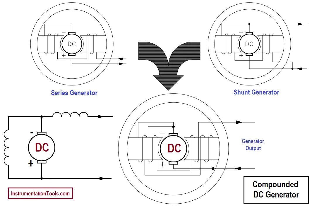
Figure 12 : Compounded DC Generator

The two windings of the compounded generator are made such that their magnetic fields will either aid or oppose one another. If the two fields are wound so that their flux fields oppose one another, the generator is said to be differentially-compounded. Due to the nature of this type of generator, it is used only in special cases and will not be discussed further in this text.

If the two fields of a compound generator are wound so that their magnetic fields aid one another, the generator is said to be cumulatively-compounded. As the load current increases, the current through the series field winding increases, increasing the overall magnetic field strength and causing an increase in the output voltage of the generator. With proper design, the increase in the magnetic field strength of the series winding will compensate for the decrease in shunt field strength.

Therefore, the overall strength of the combined magnetic fields remains almost unchanged, so the output voltage will remain constant. In reality, the two fields cannot be made so that their magnetic field strengths compensate for each other completely. There will be some change in output voltage from the no-load to full-load conditions.

In practical compounded generators, the change in output voltage from no-load to full-load is less than 5 percent. A generator with this characteristic is said to be flat-compounded (Figure 13).

Voltage versus Current for a Compounded DC Generator

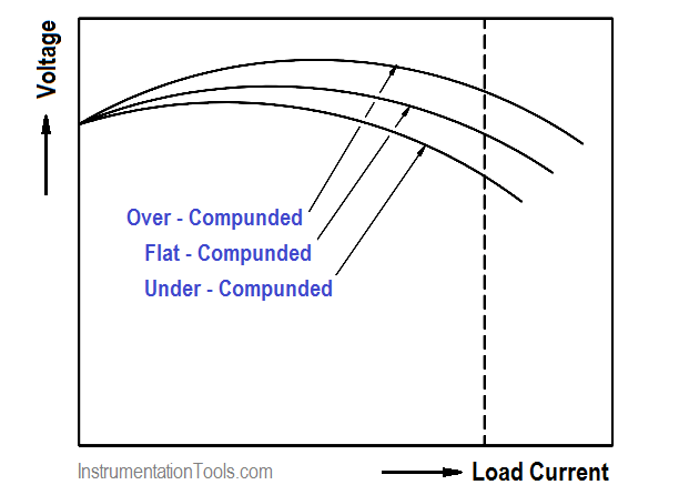
Figure 13 : Voltage-vs-Current for a Compounded DC Generator

For some applications, the series winding is wound so that it overcompensates for a change in the shunt field. The output gradually rises with increasing load current over the normal operating range of the machine. This type of generator is called an over-compounded generator.

The series winding can also be wound so that it under-compensates for the change in shunt field strength. The output voltage decreases gradually with an increase in load current. This type of generator is called an under-compounded generator.

Don't Miss Our Updates
Be the first to get exclusive content straight to your email.
We promise not to spam you. You can unsubscribe at any time.
Invalid email address
You've successfully subscribed !

Continue Reading

Starting of DC Motors
Resonance, Resonant Frequency, Series and Parallel Resonance
Voltmeters
Calculate Power in Parallel RCL Circuit
Kirchhoff’s Laws
Transformer Voltage Ratio
Share This Article
Facebook Whatsapp Whatsapp LinkedIn Copy Link
Share
Leave a Comment

Leave a Reply Cancel reply

Your email address will not be published. Required fields are marked *

Stay Connected

128.3kFollowersLike
69.1kFollowersFollow
210kSubscribersSubscribe
38kFollowersFollow

Categories

Explore More

Single Phase Power Wiring Schemes
Schematic Diagram
Resistance in Parallel Circuits
Types of Capacitors
Power Factor
Ohm Meter
Y and Delta Resistor Network Calculations
Methods of Producing Voltage (Electricity)

Keep Learning

Basic AC Generator

AC Generator Parts

Simple RL Circuit

Impedance in RL Circuits

Battery Hazard

Battery Hazards

Parallel Open Circuit Fault

Parallel Open Circuit Faults

Transformer Efficiency and Loses Formula

Transformer Losses and Efficiency

Shunt-Wound DC Motor

Shunt-Wound Motor Operation

DC Circuit Node Equations

DC Circuit Analysis Node Equations

Electric Short Circuit

Electric Circuit : Open & Short Circuits

Learn More

Marshalling Panel

What is Marshalling Cabinet?

Selection Criteria of PH Analyzer

Selection Criteria of pH Analyzers

baffle-and-nozzle assembly

Pneumatic Sensing Elements

Use of Isolator in Microwaves

Use of Isolator in Microwaves

How to Test a Motor using Megger

How to Test a Motor using Megger?

Ladder Logic Counters Instruction

Up Counter PLC Program

Advantages of Three Phase System Compared to Single Phase System

Advantages of Three Phase System Compared to Single Phase System

Compression load cell Principle

Types of Load Cells

Menu

  • About
  • Privacy Policy
  • Copyright

Quick Links

  • Learn PLC
  • Helping Hand
  • Part Time Job

YouTube Subscribe

Follow US
All rights reserved. Reproduction in whole or in part without written permission is prohibited.
Welcome Back!

Sign in to your account

Username or Email Address
Password

Lost your password?