Inst ToolsInst ToolsInst Tools
  • Courses
  • Automation
    • PLC
    • Control System
    • Safety System
    • Communication
    • Fire & Gas System
  • Instrumentation
    • Design
    • Pressure
    • Temperature
    • Flow
    • Level
    • Vibration
    • Analyzer
    • Control Valve
    • Switch
    • Calibration
    • Erection & Commissioning
  • Interview
    • Instrumentation
    • Electrical
    • Electronics
    • Practical
  • Q&A
    • Instrumentation
    • Control System
    • Electrical
    • Electronics
    • Analog Electronics
    • Digital Electronics
    • Power Electronics
    • Microprocessor
Search
  • Books
  • Software
  • Projects
  • Process
  • Tools
  • Basics
  • Formula
  • Power Plant
  • Root Cause Analysis
  • Electrical Basics
  • Animation
  • Standards
  • 4-20 mA Course
  • Siemens PLC Course
Reading: Communication Processor Module in Siemens PLC
Share
Notification Show More
Font ResizerAa
Inst ToolsInst Tools
Font ResizerAa
  • Courses
  • Design
  • PLC
  • Interview
  • Control System
Search
  • Courses
  • Automation
    • PLC
    • Control System
    • Safety System
    • Communication
    • Fire & Gas System
  • Instrumentation
    • Design
    • Pressure
    • Temperature
    • Flow
    • Level
    • Vibration
    • Analyzer
    • Control Valve
    • Switch
    • Calibration
    • Erection & Commissioning
  • Interview
    • Instrumentation
    • Electrical
    • Electronics
    • Practical
  • Q&A
    • Instrumentation
    • Control System
    • Electrical
    • Electronics
    • Analog Electronics
    • Digital Electronics
    • Power Electronics
    • Microprocessor
Follow US
All rights reserved. Reproduction in whole or in part without written permission is prohibited.
Inst Tools > Blog > PLC Tutorials > Communication Processor Module in Siemens PLC

Communication Processor Module in Siemens PLC

Communication Processor (CP) Module is used to transfer the data in a case of not having the required port on your Siemens PLC CPU.

Last updated: March 4, 2021 11:14 am
Editorial Staff
PLC Tutorials
No Comments
Share
3 Min Read
SHARE

In this article, you will learn about the CP (Communication processor) module used in the Siemens PLC.

CP module is used to transfer the data in a case of not having the required port on your CPU.

Communication Processor Module

For example, we have a redundant system installed in a plant. We have an S7-300 series of CPU 315-2DP is installed.

On the first rack, we have power supply and CPU is installed, the same way for redundancy one more CPU with power supply is installed.

On the second rack, two IMs are installed as you can see in the below window.

Communication Processor Module in Siemens PLC

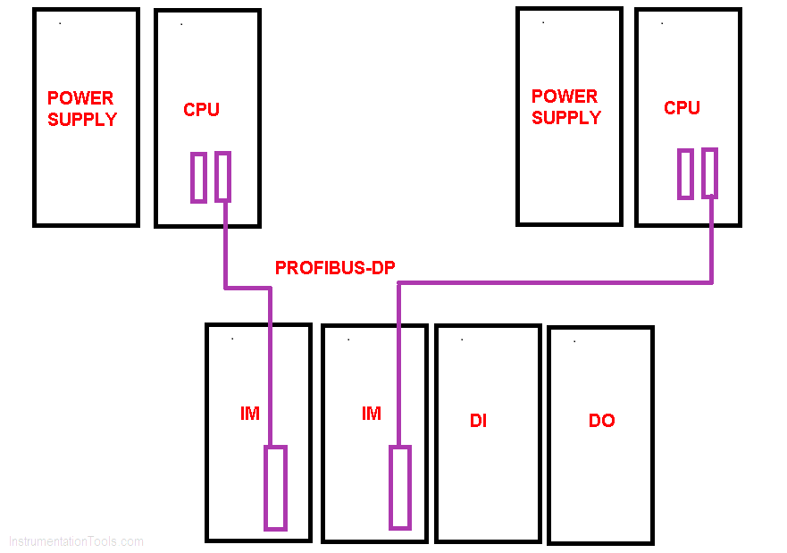
Now, both CPUs are communicating with IMs through the PROFIBUS-DP network.

But how the 1st CPU will exchange the data with the 2nd one? First, you may think of the second MP (Multi-Point Interface) to exchange the data.

But as you know MPI is a very slow network and it is not possible to send out a large amount of the data using this network.

If you use MPI to exchange the data then you only have to use the MPI network throughout the communication.

But I want to communicate or exchange the data in terms of the PROFIBUS-DP network.

To do that we have to install Simatic NET or CP having DP port on it into the rack beside the CPU as you can see in the below window.

As you can see by pulling one more PROFIBUS-DP cable with the help of the CP module and using some software arrangement you can exchange the data.

Siemens CP Module

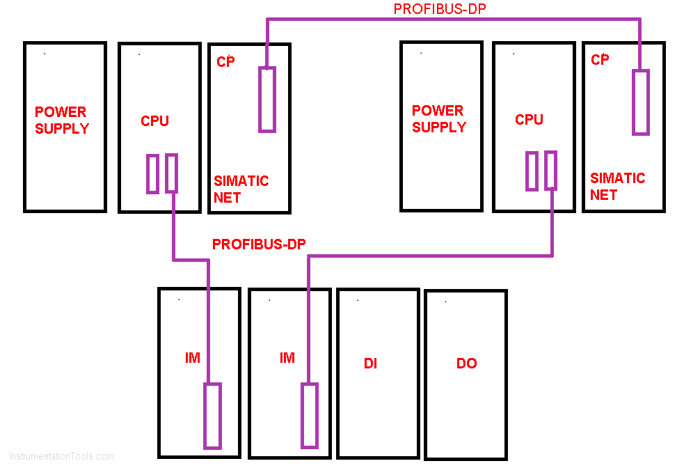
The CP module which I have shown you contains a single DP port is a CP 342-5.

There are other types of CP modules that are used that depend on an application and requirement of the network.

Other CP modules for an example are,

* CP 342-5

* CP 1243-8

* CP 343-1

* CP 443-1

* CP 342-2

Below is the image of each type of module having a different capability of communication. (PROFIBUS-DP, Ethernet, ProfiNet, etc.)

Whatever module you use, the connection technique remains the same. only the way and speed of the data exchange will differ based on the requirement.

Author: Suhel Patel

If you liked this article, then please subscribe to our YouTube Channel for PLC and SCADA video tutorials.

You can also follow us on Facebook and Twitter to receive daily updates.

Read Next:

  • Power Supply Circuits
  • Connect to the Siemens PLC
  • Digital Signals and Gates
  • What is the DDE Protocol?
  • Pulse Width Modulation
Don't Miss Our Updates
Be the first to get exclusive content straight to your email.
We promise not to spam you. You can unsubscribe at any time.
Invalid email address
You've successfully subscribed !

Continue Reading

Interposing Relay Panel (IRP) – Wiring and Testing Requirements
Communication between InTouch Scada and Allen Bradley PLC
Shift Bit Register in PLC
How to Design a System Architecture in Industrial Automation?
Site Commissioning Steps for PLC Programmers
PLC Programming for Pumping and Draining System
Share This Article
Facebook Whatsapp Whatsapp LinkedIn Copy Link
Share
Leave a Comment

Leave a Reply Cancel reply

Your email address will not be published. Required fields are marked *

Stay Connected

128.3kFollowersLike
69.1kFollowersFollow
208kSubscribersSubscribe
38kFollowersFollow

Categories

Explore More

Troubleshooting a 4-20mA Current loop
Free PLC Training Software Download
Procedure for Reading or Searching the Tag number in Siemens PLC
How to Work with Allen Bradley RsLogix Emulator?
#5 PLC Best Practices – Cryptographic and Checksum Integrity Checks
Troubleshoot Allen Bradley PLC Logic
How to Filter Digital and Analog Inputs in a PLC?
PLC Raw Count Calculation for Pressure Transmitter

Keep Learning

Difference Between Wifi and Industrial Wireless

Difference Between Wifi and Industrial Wireless

Tags in Functional Block Diagram in Studio 5000

Sheets, Tags, Elements in Functional Block Diagram of Studio 5000

How a PLC communicates with Transmitters

How PLC Reads the Data from Field Transmitters

RSlogix 500 to communicate with Excel

How to Communicate with Excel from RsLinx?

PLC Sequential Lights Control Example

PLC Timer Example: Sequential Control of Three Lights with Reset

PLC Motor Logic

Interconnection between PLC, MCC, LCP & Pumps – Video

Normally closed input actuator as stop button.

Normally-Closed Contacts for Stop Buttons

PLC Totalizer

PLC Program for Flow Totalizer

Learn More

Synchronous Motor Starting Methods

Shift Registers and Counters Objective Questions

Shift Registers and Counters Objective Questions

pH and ORP eBook Download

pH and ORP Learning Handbook

Identify Valve Parts Quiz with Answers

Identify Valve Parts Quiz with Answers

Basics of Sinking and Sourcing

Basics of Sinking and Sourcing – Automation System MCQ

Loop Current Step Response (LCSR) Test for RTD

Response Time Test of RTD and Thermocouple

Hydrostatic pressure Measurement

Basics of Hydrostatic Level Measurement

PID Controllers with output high select Logic

PID Controllers with Output High Select Logic

Follow US
All rights reserved. Reproduction in whole or in part without written permission is prohibited.
Welcome Back!

Sign in to your account

Username or Email Address
Password

Lost your password?