Inst ToolsInst ToolsInst Tools
  • Courses
  • Automation
    • PLC
    • Control System
    • Safety System
    • Communication
    • Fire & Gas System
  • Instrumentation
    • Design
    • Pressure
    • Temperature
    • Flow
    • Level
    • Vibration
    • Analyzer
    • Control Valve
    • Switch
    • Calibration
    • Erection & Commissioning
  • Interview
    • Instrumentation
    • Electrical
    • Electronics
    • Practical
  • Q&A
    • Instrumentation
    • Control System
    • Electrical
    • Electronics
    • Analog Electronics
    • Digital Electronics
    • Power Electronics
    • Microprocessor
Search
  • Books
  • Software
  • Projects
  • Process
  • Tools
  • Basics
  • Formula
  • Power Plant
  • Root Cause Analysis
  • Electrical Basics
  • Animation
  • Standards
  • 4-20 mA Course
  • Siemens PLC Course
Reading: Closed Tank Remote Seal Capillary type DP Transmitter
Share
Notification Show More
Font ResizerAa
Inst ToolsInst Tools
Font ResizerAa
  • Courses
  • Design
  • PLC
  • Interview
  • Control System
Search
  • Courses
  • Automation
    • PLC
    • Control System
    • Safety System
    • Communication
    • Fire & Gas System
  • Instrumentation
    • Design
    • Pressure
    • Temperature
    • Flow
    • Level
    • Vibration
    • Analyzer
    • Control Valve
    • Switch
    • Calibration
    • Erection & Commissioning
  • Interview
    • Instrumentation
    • Electrical
    • Electronics
    • Practical
  • Q&A
    • Instrumentation
    • Control System
    • Electrical
    • Electronics
    • Analog Electronics
    • Digital Electronics
    • Power Electronics
    • Microprocessor
Follow US
All rights reserved. Reproduction in whole or in part without written permission is prohibited.
Inst Tools > Blog > Formulas > Closed Tank Remote Seal Capillary type DP Transmitter

Closed Tank Remote Seal Capillary type DP Transmitter

Last updated: April 19, 2019 4:15 pm
Editorial Staff
Formulas Level Measurement Pressure Measurement
4 Comments
Share
5 Min Read
SHARE

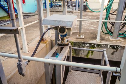
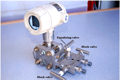
A remote seal capillary type dp transmitter which is mounted on a closed tank. distance between both flanges is 1835 mm and density of fluid in tank is 1.15, transmitter is mounted below the high side flange. please give the calculation of URV and LRV values.

Answer

You need to know the capillary fill fluid specific gravity to make the calculation.

Calculating LRV and URV for dual remote seals on a closed tank

Assuming

  • the minimum level is 4mA
  • the maximum level is 20mA
  • high side port is at the bottom tap
  • low side port is at the top tap

The ranging of a remote seal transmitter is not guesswork, it is an arithmetic (multiplication and subtraction) calculation requiring four or five values that are specific to the application:

  • specific gravity (SG) of remote seal fill fluid (SGf value)
  • specific gravity of the process liquid (SGp value)
  • Elevation distance between taps, the lower seal (high side) and upper seal (low side) (d value)
  • distance between bottom tap and maximum level height (what 20mA represents) (b value)
  • distance between bottom tap and minimum level (what 4mA represents) (a value)

It does not matter whether the transmitter is at, below or above the bottom tap when dual remote seals are used. The LRV and URV are the same for all three conditions.

Refer to the illustration:

remote seal capillary type dp transmitter

LRV = (SGp * a) – (SGf * d)

URV = (SGp * b) – (SGf * d)

In many cases, the lower level (4mA) is where the bottom tap is, so value a = zero.

When a = 0, then (SGp * 0) = 0.

Hence, LRV = 0 – (SGf * d), which results in a negative value.

That’s correct. Do not be surprised if the LRV is a negative value. It frequently is negative, as well as the URV.

Remote seal transmitters assembled and filled by the manufacturer will have a part number that includes a code for the fill fluid and usually the tag will show the fill fluid too.

Commonly used capillary fill fluid specific gravities range from 0.26 for glycerin to 1.97 for Halocarbon. Guessing at the fill fluid can lead to large and significant errors. Determine the actual fill fluid.

Example: Dual remote seals on closed tank

a = 0 (bottom tap is minimum level point)
b = 108 inches (maximum liquid level)
d = 120 inches (elevation distance between the high and low taps)
SGp = tank fluid SG = 0.95
SGf = fill fluid SG = 0.934

1) Calculate the LRV

LRV = (SGp * a) – (SGf * d)

At min level (empty), there is 0 process liquid pressure on the high side, so SGp = 0.

A = 0, so (SGp * a) = 0″

The fill fluid exerts a pressure of (SGf * d) or (0.923 * 120″) on the low side

(SGf * d) = 0.934 * 120″ = 112.08″

LRV = (SGp * a) – (SGf * d)

LRV = 0″ – 112.08″ = -112.08″

LRV = -112.08

2) Calculate the URV

URV = (SGp * b) – (SGf * d)

At the maximum fluid level, there is a pressure of (SGp * b), or (0.95 * 108″) on the high side.

(SGp * b) = 0.95 * 108″ = 102.6″

URV = (SGp * b) – (SGf * d)

102.6″ – 112.08″ = – 9.48″

URV = -9.48

3) Transmitter’s range

LRV = 4mA = -112.80″ w.c.

URV = 20mA = -9.48″ w.c.

The transmitter’s range is -112.08″ to -9.48″ w.c., a span of 102.6″ w.c., which is the head pressure of 108″ of liquid with a SG of 0.95.

Articles You May Like :

Remote Seals Configuration

Guided Wave Radar Level Sensor

RF Admittance Level Transmitter

Capacitive Level Switch Principle

Level Troll working principle

Don't Miss Our Updates
Be the first to get exclusive content straight to your email.
We promise not to spam you. You can unsubscribe at any time.
Invalid email address
You've successfully subscribed !

Continue Reading

Remote Seal Differential Pressure Transmitters Principle
Difference between Transparent Level Gauge and Reflex Level Gauge
Pressure Sensor Specifications
DP Transmitters Level Measurement Principle Video
Basics of DP Transmitter Suppression and Elevation
Bubbler Level Measurement Animation
Share This Article
Facebook Whatsapp Whatsapp LinkedIn Copy Link
Share
4 Comments
  • Azfar Yusof says:
    May 3, 2016 at 3:01 pm

    Hai there, what happen if the transmitter located higher than top tapping (low tapping)? Can you explain the calculation?

    Reply
    • Gourav Sourav says:
      January 27, 2024 at 4:58 pm

      It does not matter whether the transmitter is at, below or above the bottom tap when dual remote seals are used. The LRV and URV are the same for all three conditions.

      Reply
  • Jigar Rana says:
    December 19, 2017 at 6:21 am

    sir, how can we define the Distance of maximum liquid level (B)?

    Reply
    • Jigar Rana says:
      December 19, 2017 at 6:27 am

      Hello sir, how can i define the minimum level (a) , maximum level (b) and also at which point i have to take Hish side and low side tapping.

      Give me reply sir As soon as Possible

      Reply

Leave a Reply Cancel reply

Your email address will not be published. Required fields are marked *

Stay Connected

128.3kFollowersLike
69.1kFollowersFollow
208kSubscribersSubscribe
38kFollowersFollow

Categories

Explore More

Pressure Transmitter Preventive Maintenance
How to Convert Cable Size from AWG to Inches
Pressure Gauges with Capsule Sensor Principle
What is Static Pressure Limit in DP Transmitter ?
Capacitive Type Pressure Transducers Principle
The Principle of Dead Weight Pressure Tester
Cable Float Level Switch Working Principle
Siemens Pressure Transmitter with Remote Seals Calculations

Keep Learning

Fieldbus Pressure Transmitter Configuration

Foundation Fieldbus Pressure Transmitter Configuration

Field Transmitter Range Calculation

Transmitter Turndown Ratio, Set Span and Zero Span

Helix and Spiral Tubes - Pressure Sensor

Helix and Spiral Tubes – Pressure Sensor

Impulse Line Problems

What are Impulse Lines? – Impulse Line Problems & Solutions

Uncertainty Calculations of Pressure Calibration

Uncertainty Calculations of Pressure Calibration

Level Gauges

Level Gauge Design

Overview of Tank Gauging Technologies

Float Level Switch Principle

Float Level Switch Working Principle Animation

Learn More

Relief Valve

Pressure Relief Valve Principle

Impulse Line Problems

What are Impulse Lines? – Impulse Line Problems & Solutions

Weigh Feeder Drive

Failing Weigh Feeders and Mechanical Variable Speed Drives (VSD)

Gas Detectors Bump Testing

What is Bump Testing ?

LVDT-Operation-Principle-Animation

LVDT Working Principle Animation

liquid flow control system

Practical Process Control System Questions & Answers – 7

Instrumentation During the Detail Design Phase

Instrumentation Engineer Activities & Documents – Detail Design Phase

Difference between Radio Waves and Microwaves

Difference between Radio Waves and Microwaves

Follow US
All rights reserved. Reproduction in whole or in part without written permission is prohibited.
Welcome Back!

Sign in to your account

Username or Email Address
Password

Lost your password?