Inst ToolsInst ToolsInst Tools
  • Courses
  • Automation
    • PLC
    • Control System
    • Safety System
    • Communication
    • Fire & Gas System
  • Instrumentation
    • Design
    • Pressure
    • Temperature
    • Flow
    • Level
    • Vibration
    • Analyzer
    • Control Valve
    • Switch
    • Calibration
    • Erection & Commissioning
  • Interview
    • Instrumentation
    • Electrical
    • Electronics
    • Practical
  • Q&A
    • Instrumentation
    • Control System
    • Electrical
    • Electronics
    • Analog Electronics
    • Digital Electronics
    • Power Electronics
    • Microprocessor
  • Request
Search
  • Books
  • Software
  • Projects
  • Process
  • Tools
  • Basics
  • Formula
  • Power Plant
  • Root Cause Analysis
  • Electrical Basics
  • Animation
  • Standards
  • 4-20 mA Course
  • Siemens PLC Course
Reading: Circuit Breaker Working Principle Animation
Share
Font ResizerAa
Inst ToolsInst Tools
Font ResizerAa
  • Courses
  • Design
  • PLC
  • Interview
  • Control System
Search
  • Courses
  • Automation
    • PLC
    • Control System
    • Safety System
    • Communication
    • Fire & Gas System
  • Instrumentation
    • Design
    • Pressure
    • Temperature
    • Flow
    • Level
    • Vibration
    • Analyzer
    • Control Valve
    • Switch
    • Calibration
    • Erection & Commissioning
  • Interview
    • Instrumentation
    • Electrical
    • Electronics
    • Practical
  • Q&A
    • Instrumentation
    • Control System
    • Electrical
    • Electronics
    • Analog Electronics
    • Digital Electronics
    • Power Electronics
    • Microprocessor
  • Request
Follow US
All rights reserved. Reproduction in whole or in part without written permission is prohibited.
Inst Tools > Blog > Animation > Circuit Breaker Working Principle Animation

Circuit Breaker Working Principle Animation

Last updated: March 31, 2019 11:28 am
Editorial Staff
Animation Electrical Basics
No Comments
Share
5 Min Read
SHARE

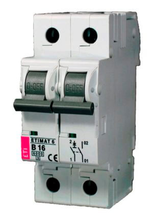
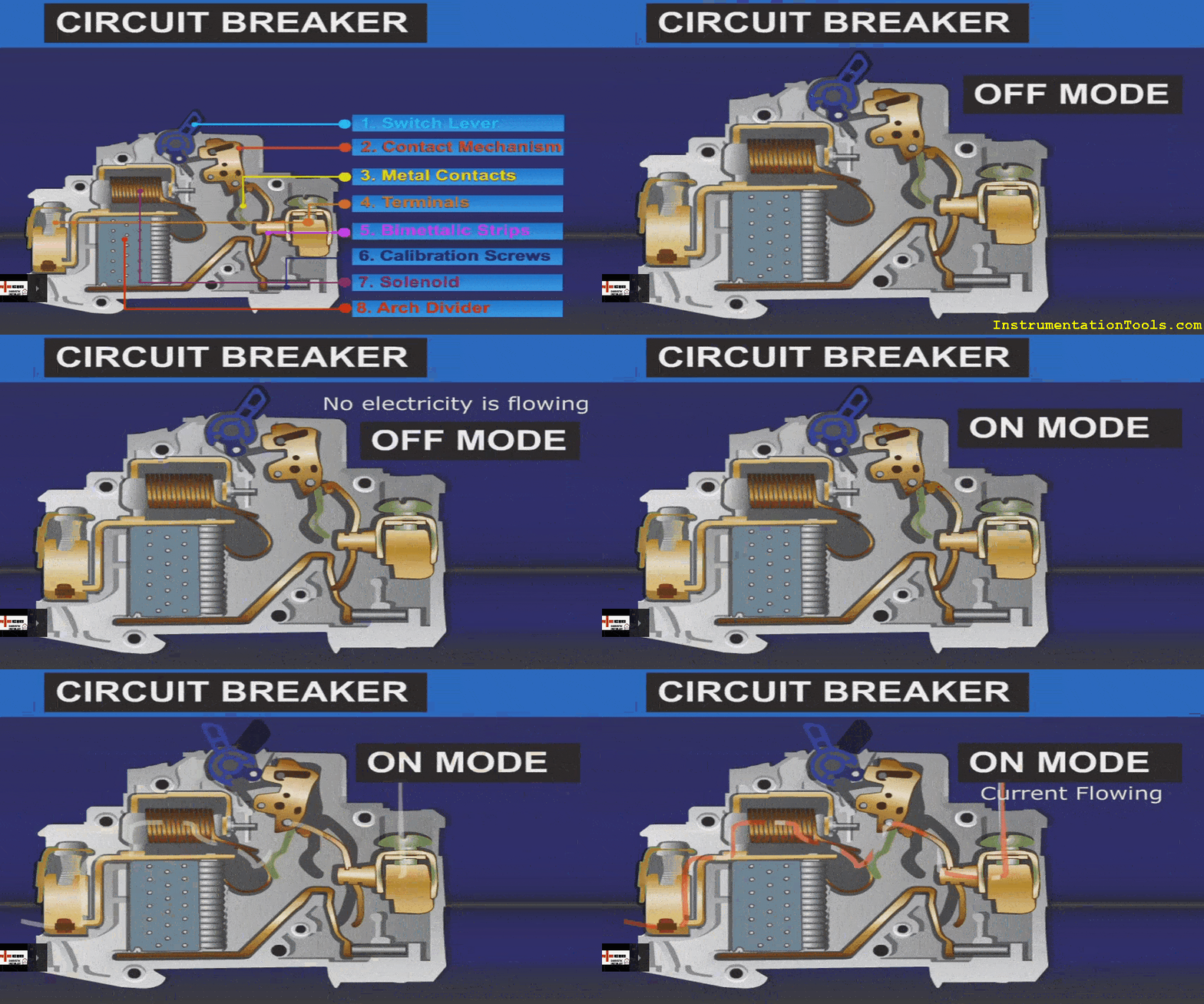
A circuit breaker is an automatically-operated electrical switch designed to protect an electrical circuit from damage caused by overload of electricity or short circuit. A circuit breakers function is to detect a fault condition and, by interrupting continuity, to immediately discontinue electrical flow.

Contents
Circuit Breaker AnimationIntroduction to Circuit BreakerDefinition of circuit breakerOperating principle of Circuit breakerCircuit breaker main purposeAdvantages of Circuit breaker over fuse

Circuit Breaker Animation

Circuit Breaker Animation

Introduction to Circuit Breaker

In the Power system operation it is often desirable and necessary to break or interrupt the various devices or transmission lines under normal and abnormal conditions. In the earlier days switches and fuses are used for this purpose to break or close the contact.

But if the fuse breaks on fault then it will take time to replace it which causes a large interrupt to power transmission. The operator has to go the field to replace the fuse once it fails. The switches or fuses cannot withstand high currents because of their construction.

Introduction to Circuit Breaker

These disadvantages of the switches and fuses made them to use in lower voltage range. But in emerging electrical engineering every day we are dealing with new technology consist of higher voltage range which prompted to use the device called circuit breaker.

Definition of circuit breaker

Circuit breaker is a device which makes the circuit when the operator intends it and which breaks the circuit based on operator intention as well as for any fault in the circuit.

The summarized important functions of circuit breakers are as follows:
  1. The circuit breaker can be operated manually or remotely from control room.
  2. The Circuit breaker can operate under fault conditions automatically through logic circuit.
  3. It can withstand for higher voltages providing higher insulation between two contacts when it is open.

Operating principle of Circuit breaker

It is necessary to know how the circuit breaker works for every electrical engineer. Circuit breaker consists of two electrodes one is fixed and another moving. The circuit will be closed if the two contacts are in contact and it will be open when these are two are apart.

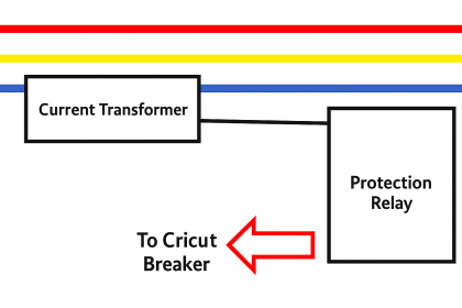
This is based on the operator requirement whether the circuit should be closed or opened at the initial case. Suppose if the breaker is closed initially to make the circuit, if any fault occurs in the circuit or if the operator wanted to open it then the logic signal energizes the trip relay which separates the two contacts by moving the moving coil distant to the fixed coil.

This looks easy operation but the real hurdle is here only i.e. when the two contacts are separating there will be large transient potential difference between the contact ends which enables huge electron jumping from high potential to low potential. But the transient distance between the two contacts at that instant acts as dielectric for the electrons to pass from one electrode to another electrode.

 If the potential difference is higher than the dielectric strength then the electrons tries to pass to another electrode which ionizes the dielectric medium which leads to high spark between the electrodes. This spark is called “arc” between the electrodes.

Even though the arc persists for microseconds, it is sufficient to blast the circuit breaker insulating casing and components in it due to the high heat of sparking.

So to avoid this damage to the circuit breaker the severity of the arc has to reduce by increasing the dielectric strength between the two electrodes when they are separating and the developed has to quench immediately before it damages the breaker.

The mediums like Air, oil, vacuum and SF6 (Sulfur Hexa fluoride) are used as arc quenching mediums which offers high dielectric strength as well as quench the arc as soon as possible.

Circuit breaker main purpose

  • Switch load currents
  • Make onto a fault
  • Break normal and fault currents
  • Carry fault current without blowing itself open (or up!) i.e. no distortion due to magnetic forces under fault conditions.
  • The important characteristics from a protection point of view are: The speed with which the main current is opened after a tripping impulse is Received.

Advantages of Circuit breaker over fuse

  • The Circuit breaker operates at high voltages compared to fuse.
  • Circuit breaker can be operated remotely by energizing the close or trip coil which cannot be done in case of fuse.
  • Circuit breaker functioning (Tripping or closing) can be tested easily.
  • No need to replace the circuit breaker after fault.
Don't Miss Our Updates
Be the first to get exclusive content straight to your email.
We promise not to spam you. You can unsubscribe at any time.
Invalid email address
You've successfully subscribed !

Continue Reading

Guided-wave Radar Level Measurement Animation
Main differences between Sinking and Sourcing Circuits
Distributed Temperature Sensors (DTS) in Power Lines
Current Transformer Selection, Operation & Maintenance
Proximity switches Circuit Diagram Operation
Air Filter Regulator Working Principle Animation
Share This Article
Facebook Whatsapp Whatsapp LinkedIn Copy Link
Share
Leave a Comment

Leave a Reply Cancel reply

Your email address will not be published. Required fields are marked *

Stay Connected

128.3kFollowersLike
69.1kFollowersFollow
210kSubscribersSubscribe
38kFollowersFollow

Categories

Explore More

Electric Stress Control in Cables, Joints, and Terminations
Difference Between MCB and RCBO
Argonite Fire Suppression System Working Principle
What is an Inductor? – Types of Inductors
Electrical Switches Principle & Types
How a 4-20mA Transmitter Works?
Root Cause Analysis – Burst Transformers and 11 kV Input Breakers
Acceptable Earth Resistance Values

Keep Learning

Logic Gates Symbols & Truthtables

Logic Gates Animation

Bubbler Level Measurement Animation

Bubbler Level Measurement Animation

What is an HRC Fuse

What is an HRC Fuse? – Material, Types, Advantages

Flow Switch Working Principle Animation

Working Principle of Flow Switch with Animation

open vs closed loop

Open Loop and Closed Loop Animation

NO NC Contact Animation

Equivalent Logic Gates using PLC Ladder Diagrams

Phase Failure Relay

Why is Phase Failure Relay Required in LV Panels?

Level-Transmitters-Animation

Level Transmitter Animation

Learn More

How to Solve Cable Tray Sagging

How to Solve Cable Tray Sagging ?

Analyzer Sample Conditioning

Sodium Analyzer Problems and Troubleshooting Steps

Valve Positioner Torn apart

Pipeline Shakes Torn apart Valve Positioners

Failsafe interlock Design

Failsafe Wiring Practices

Auto Recloser Circuit Breaker in Power System

Auto Recloser Circuit Breaker in Power System

PLC Programming for Tank Farm Management

Tank Farm Management System: CX-Programmer [OMRON]

PLC Program for Star Delta Starter using Functional Block Diagram

PLC Program for Star Delta Starter using Functional Block Diagram

Direct Acting Actuators

Effect of Differential Pressure on Control Valve Lift

Menu

  • About
  • Privacy Policy
  • Copyright

Quick Links

  • Learn PLC
  • Helping Hand
  • Part Time Job

YouTube Subscribe

Follow US
All rights reserved. Reproduction in whole or in part without written permission is prohibited.
Welcome Back!

Sign in to your account

Username or Email Address
Password

Lost your password?