Study about the calibration procedure of voltmeter and ammeter using master instruments like multi-function calibrators.
What is Voltmeter?
A Voltmeter is also known as a Voltage Meter, it is an instrument used for measuring the potential difference or voltage between two points in an electrical or electronic circuit. They can be used in AC/DC circuits.
Symbolic Representation:
What is Ammeter?
An Ammeter is also known as an Ampere Meter, it is an instrument used for measuring the current. The measuring range of the ammeter depends on the resistance (CT) inside the Ammeter.
Symbolic Representation:
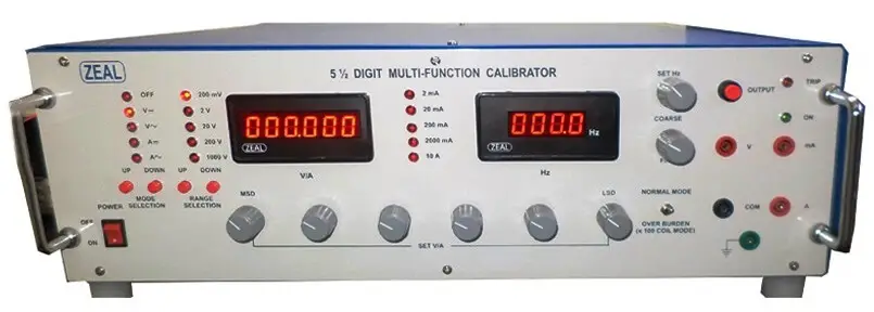
Master Instruments With Auxiliary:
Multi-Function Calibrator (5 ½ MFC)
The Multi-Function Calibrator (MFC) is the instrument used as a source supplier for AC/DC voltage and Current for the calibration of all the electrical related devices.
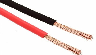
Wires
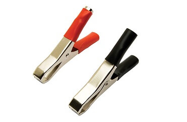
Crocodile Pins
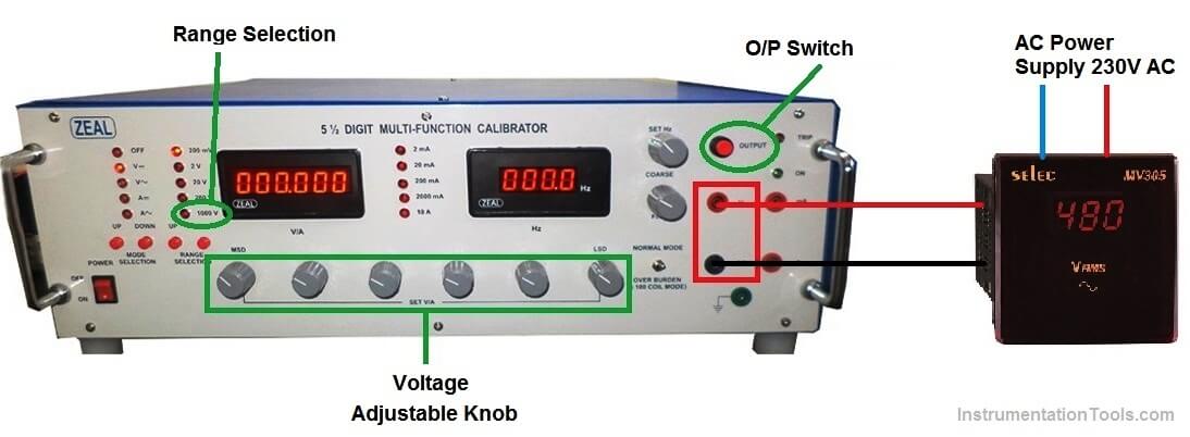
Setup for Voltmeter
Voltmeter Calibration Procedure
We will perform the individual calibration of Voltmeter and Ammeter.
1. Connect the wire with the help of crocodile pin to Voltmeter one end and other to the 5 ½ MFC meter as shown in the above Setup picture.
2. Here we will keep the Source meter i.e. 5 ½ MFC meter as a fixed voltage supplier and will see the reading on the UUC (Unit Under Calibration – voltmeter)
3. Suppose we have a Voltmeter with Specification.
- Make- Selec
- Range-0 to 400V AC
- Least Count- 0.1V AC
4. We will supply the AC voltage with the help of Knob provided on the 5 ½ MFC meter in the increment of 50V AC. i.e. 50,100,150,200,250 VAC etc.
5. And will record what is the UUC instrument is displaying on its display.
6. Repeat the 4th step till the Max limit of Voltmeter Range reaches.
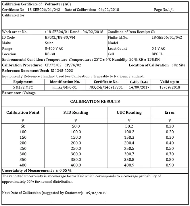
Calibration Certificate of Voltmeter
Setup for Ammeter
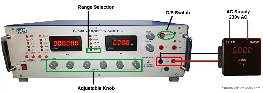
Ammeter Calibration Procedure
1. Connect the wire with the help of crocodile pin to Ammeter one end and other to the 5 ½ MFC meter as shown in the above Setup picture.
2. Here we will keep the Source meter i.e. 5 ½ MFC meter as a fixed Ampere supplier and will see the reading on the UUC (Unit Under Calibration)
3. Suppose we have an Ammeter with Specification.
- Make- Selec
- Range-0 to 10 Amp DC
- Least Count- 1 Amp DC
4. We will supply the DC Current with the help of Knob provided on the 5 ½ MFC meter in the increment steps like i.e. 2, 4, 6, 8, 10.
5. And will record what is the UUC instrument (ammeter) is displaying on its display.
6. Repeat the 4th step till the Max limit of Ammeter Range reaches.
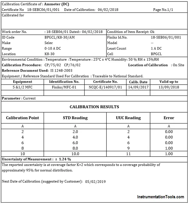
Calibration Certificate of Ammeter
Author: Jadhav Amit R
Read Next:
- Digital Control Valve Calibration
- Pressure Gauge Calibration
- Analyzer Principle and Calibration
- Portable Gas Detectors Calibration
- Turbidity Sensor Calibration