Bubbler Liquid Level Transmitter Calculation
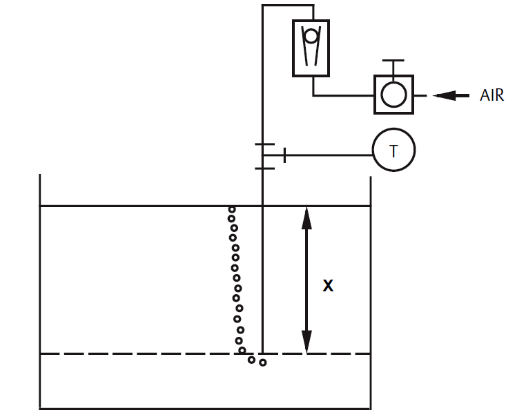
Image Credits : Rosemount
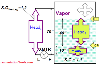
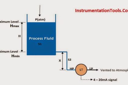
Let X equal the vertical distance between the minimum and maximum measurable levels (100 in.).
Let SG equal the specific gravity of the fluid (1.1).
Let h equal the maximum head pressure to be measured in inches of water.
Let Range equal zero to h.
Then
h = (X)(SG)
= 100 x 1.1
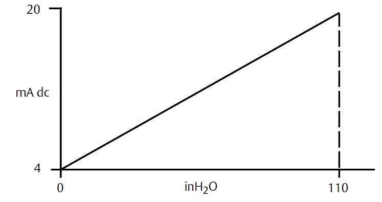
= 110 inH2O
Range = 0 to 110 inH2O
Source : Rosemount


Thank you for the information. How do one determine the amount of air flow from the rotameter to he pressure transmitter? Is there a calculation for this
As per my understanding, 40 bubbles per minute is standard.
It is my understanding that the purge rate isn’t critical. Typically set at 1-2 scfh.