In this article, we are going to discuss the concept of interlocks in boilers.
For the safe operation of boiler and its auxiliaries under higher operating conditions some protection techniques are needed to be followed. These are referred to as interlocks.
What is a Boiler?
Boiler is defined as a closed metallic vessel where the steam is produced by heating water above the atmospheric pressure by the application of heat generated by the combustion of fuelsin the presence of oxygen.
Definition of boilers as per Indian Boiler act (IBR).
According to IBR.
“The boiler is a closed metallic vessel with the design capacity of more than 22.75 liters of water & pressure of above 3.5 kg/cm² is used to generate steam under pressure, with installed mountings to it. And maintaining a pH of Boiler feed water between 8.5 to 9.5.”
What is an Interlock?
An Interlock is a feature that makes two or more machines or devices mutually dependent to each other to prevent the damage of apparatus or devices from undesired conditions. These dependent machines or equipment can be electrical, electronic or mechanical devices.
Generally, Interlocks are considered as start permissive of any equipment that depends on others.
What is Protection?
The possibility of preventing the damaging of any machinery equipment or a system. System protection is most necessary to safeguard the machine against undesired damages of machines or equipment. And unusual fluctuation of process parameters to unacceptable value
What are the types of Interlocks?
Generally, interlocks can be categorized as
- Process Interlock
- Safety Interlock
What is the purpose of using Interlocks?
The primary purpose of interlocks is to protect or safeguard the equipment against abnormal deviation of process parameters to unacceptable values.
Interlocking can be controlled by using suitable sensors and probes to avoid unusual or harmful damage to equipment.
Interlocking units and Reasons for Tripping and measures to avoid tripping of Boiler equipment are shown below
Boiler Feed Pump
Reason or Cause of Tripping: To avoid low pressure at suction side of BFP.
Minimum Value required to avoid Tripping: The De aerator level must be above 20 % of range and suction pressure must be maintained above 1.5 Kg/cm2.
Reason or Cause of Tripping: To facilitate proper flooding of feed water to feed pumps.
Minimum Value required to avoid Tripping: Differential Pressure must be maintained to 3000 mmwc i.s. 0.3 kg/cm2
Boiler Feed Pump
Inter-Related Unit: Auxiliary Cooling Water (ACW) Pump.
Reason or Cause of Tripping: To facilitate the pressure of cooling water for proper cooling of mechanical seal and bearings.
Minimum Value required avoiding Tripp: Cooling water pressure must be maintained above 2.5 kg/cm2.
Reason or Cause of Tripping: To avoid ceasing of bearing due to high temperature.
Minimum Value required to avoid Tripping:
- Bearing Temperature at the Drive end must be less than 90 Degrees Celsius.
- Bearing Temperature at the Non-Drive end must be less than 110 Degrees Celsius.
Reason or Cause of Tripping: To avoid burning of motor due to high temp.
Minimum Value required for avoiding Tripping: The motor winding temperature must be less than 130 Degrees Celsius.
Screw Feeders
Inter Related Unit: O2 Analyzer
Reason or Cause of Tripping: To avoid bagasse hipping in a boiler furnace.
Minimum Value required to avoid Tripping: Must be more than 1%.
Screw Feeders
Inter Related Unit: Drum Feeder
Reason or Cause of Tripping: To avoid chute jamming.
Minimum Value required to avoid Tripping: The drum feeder motor current must be above 13 amps.
I.D Fan
Inter Related Unit: Furnace Draft Low i.e. towards negative pressure.
Reason or Cause of Tripping: For furnace safety purposes.
Minimum Value required avoiding Tripping: vacuum should not be less than 150 mmwc.
I.D Fan
Inter Related Unit: F.D Fan
Reason or Cause of Tripping: To avoid bearing failures due to high temperature and unbalance of Fan due to high vibration.
Minimum Value required to avoid Tripping:
- Bearing Temperature at the Drive end must be less than 90 Degrees Celsius.
- Bearing Temperature at the Non-Drive end must be less than 110 Degrees Celsius.
F.D Fan
Inter Related Unit: Furnace draft high i.e. towards positive pressure.
Reason or Cause of Tripping: For furnace safety purposes.
Minimum Value required to avoid Tripping: The vacuum should not be more than 150 mmwc.
F.D Fan
Inter Related Unit: Drum level low due to tripping of boiler feed water pump.
Reason or Cause of Tripping: To avoid boiler tube failure.
Minimum Value required avoiding Tripping: Boiler Drum level must be maintained to a minimum of 10% or 15%.
F.D Fan
Inter Related Unit: S.A Fan
Reason or Cause of Tripping: To avoid bearing failures due to high temperature and unbalance of the fan due to high vibration.
Minimum Value required to avoid Tripping:
- Bearing Temperature at the drive end must be less than 90 Degrees Celsius.
- Bearing Temperature at the Non-Drive end must be less than 110 Degrees Celsius.
S.A Fan
Inter Related Unit: Screw Feeder
Reason or Cause of Tripping: To avoid bagasse carry with flue gas and bagasse distribution properly in the furnace for proper combustion of fuel.
Minimum Value required avoiding Tripping: S.A Fan Pressure but be maintained for a minimum of 250 mmwc.
Reason or Cause of Tripping: To operate damper cylinders for built pressure.
Minimum Value required to avoid Tripping: Compressed air pressure must be a minimum of 3.5 Kg/cm2.
S.A Fan
Inter Related Unit: Screw Feeder
Reason or Cause of Tripping: To avoid bagasse failure due to high Temperature and Unbalance of the fan due to high vibration.
Minimum Value required to avoid Tripping:
- Bearing Temperature at the Drive end must be less than 90 Degrees Celsius.
- Bearing Temperature at the Non-Drive end must be less than 110 Degrees Celsius.
Boiler Safety and Process Interlocks
The safety and process Interlocks employed in the Sugar factory boiler are as follows
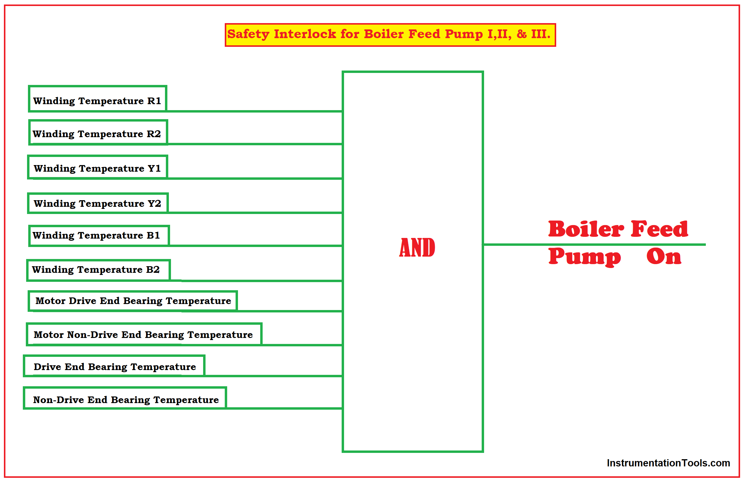
Safety Interlocks for Boiler feed Pump I, II, & III.
- Winding Temperature R1
- Winding Temperature R2
- Winding Temperature Y1
- Winding Temperature Y2
- Winding Temperature B1
- Winding Temperature B2
- Motor Drive End Bearing Temperature
- Motor Non-Drive End Bearing Temperature
- Drive End Bearing Temperature
- Non-Drive End Bearing Temperature
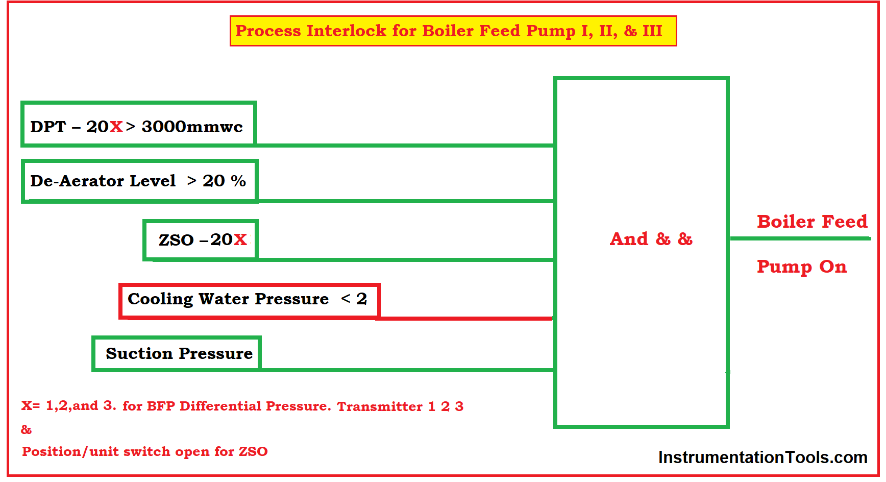
Process Interlocks for Boiler feed Pump I, II,& III.
- DPT – 20X > 3000mmwc
- Deaerator Level > 20 %
- ZSO – 20X
- Cooling Water Pressure < 2
- Suction Pressure
DPT – Differential Pressure Transmitter
ZSO – Unit Switch Open Position
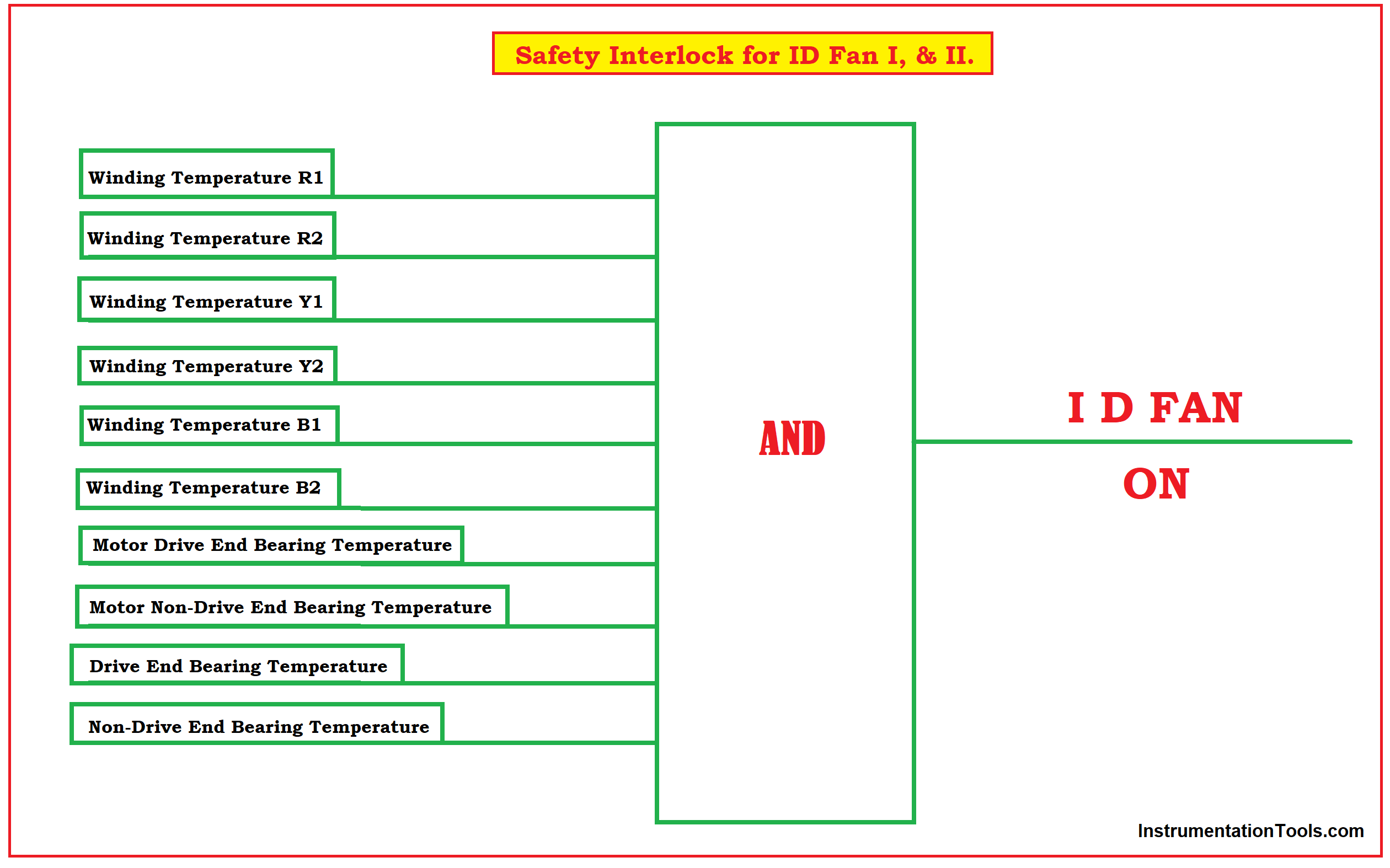
Safety Interlock for ID Fan I, & II
- Winding Temperature R1
- Winding Temperature R2
- Winding Temperature Y1
- Winding Temperature Y2
- Winding Temperature B1
- Winding Temperature B2
- Motor Drive End Bearing Temperature
- Motor Non-Drive End Bearing Temperature
- Drive End Bearing Temperature
- Non-Drive End Bearing Temperature
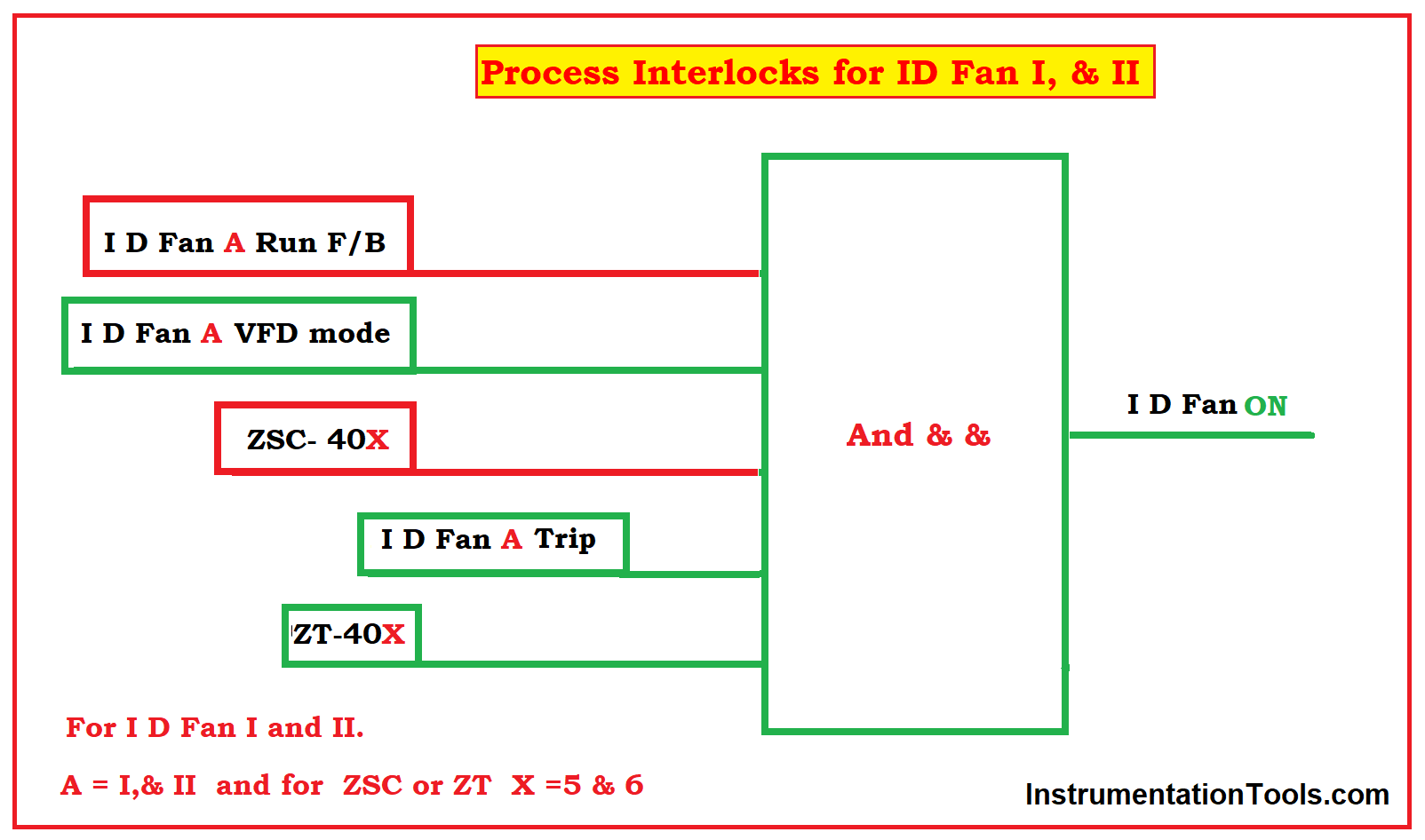
Process Interlocks for ID Fan I, & II.
- ID Fan-A Run Feedback
- ID Fan-I VFD mode
- ZSC- 40X
- ZT-40X
- ID –Fan A Trip
A = I,& II and for ZSC or ZT X =5 & 6 For ID Fan I and II.
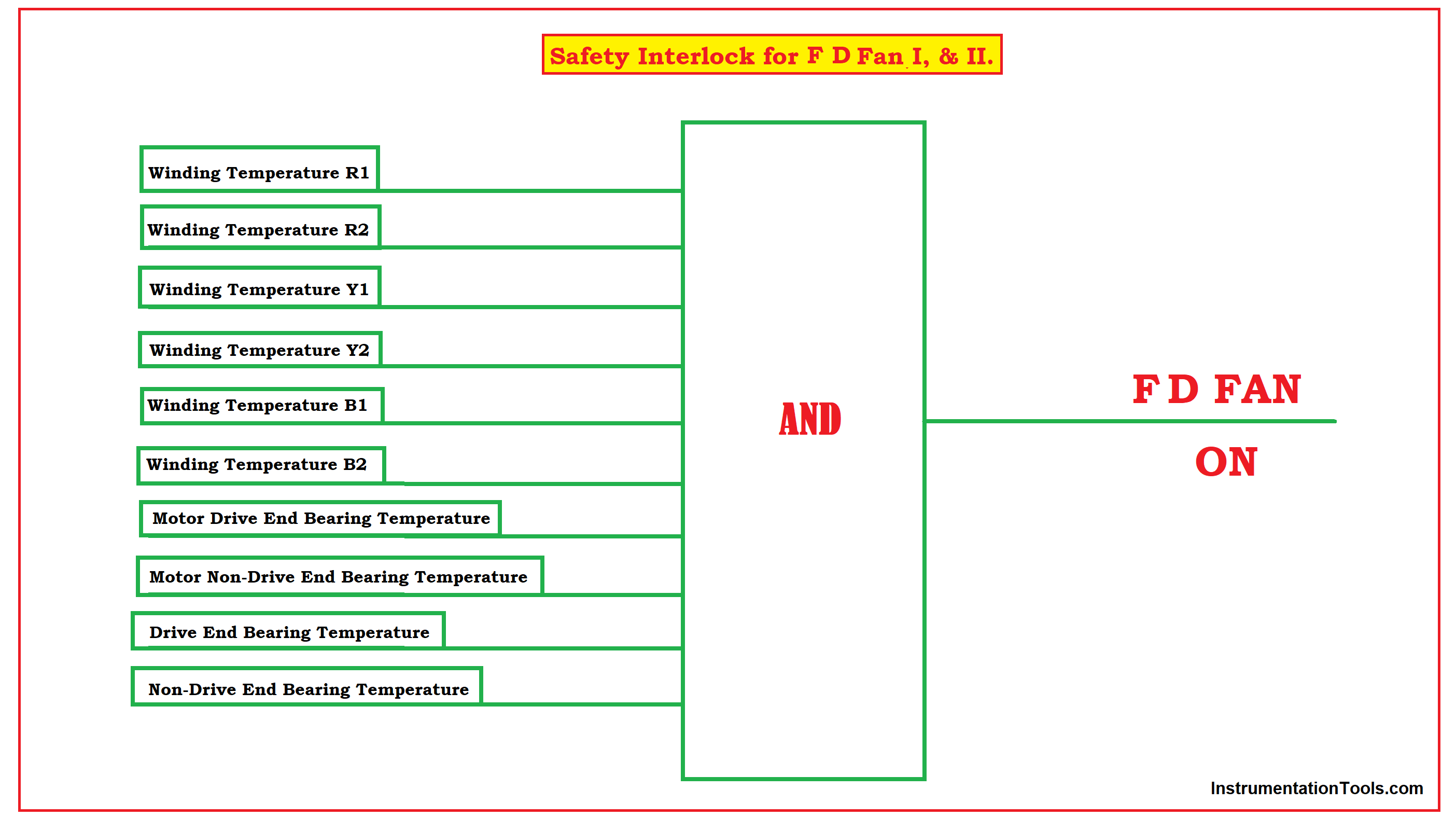
Safety Interlock for FD Fan I, & II.
- Winding Temperature R1
- Winding Temperature R2
- Winding Temperature Y1
- Winding Temperature Y2
- Winding Temperature B1
- Winding Temperature B2
- Motor Drive End Bearing Temperature
- Motor Non-Drive End Bearing Temperature
- Drive End Bearing Temperature
- Non-Drive End Bearing Temperature
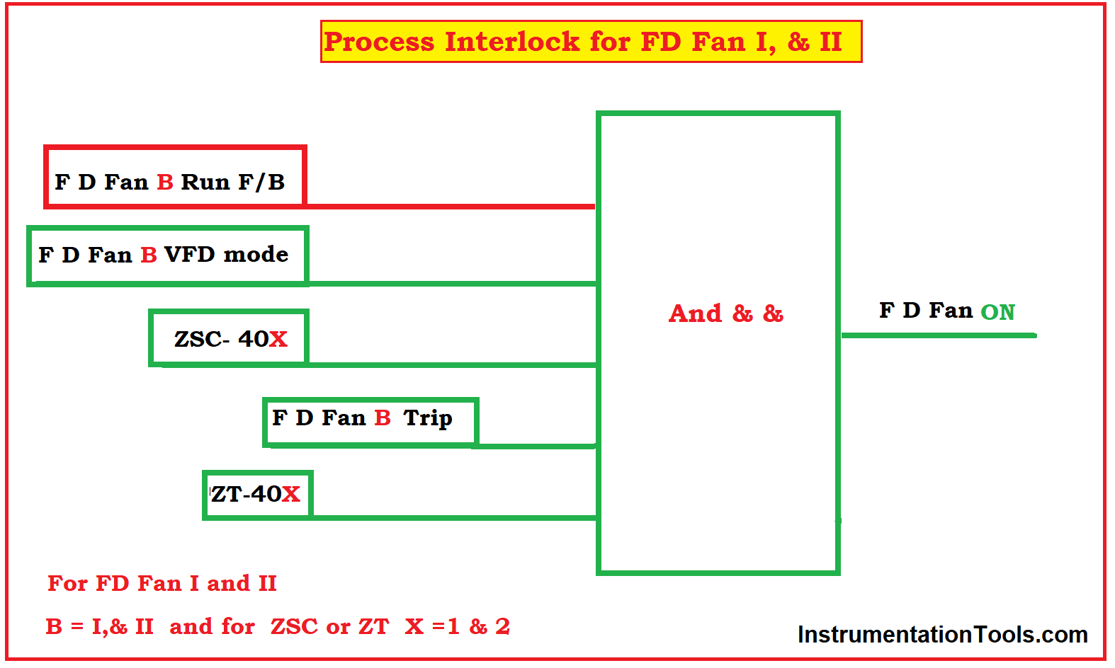
Process Interlocks for FD Fan I, & II.
- FD Fan-B Run Feedback
- FD Fan-I VFD mode
- ZSC- 40X
- ZT-40X
- FD –Fan B Trip
B = I,& II and for ZSC or ZT X =1 & 2 For FD Fan I and II
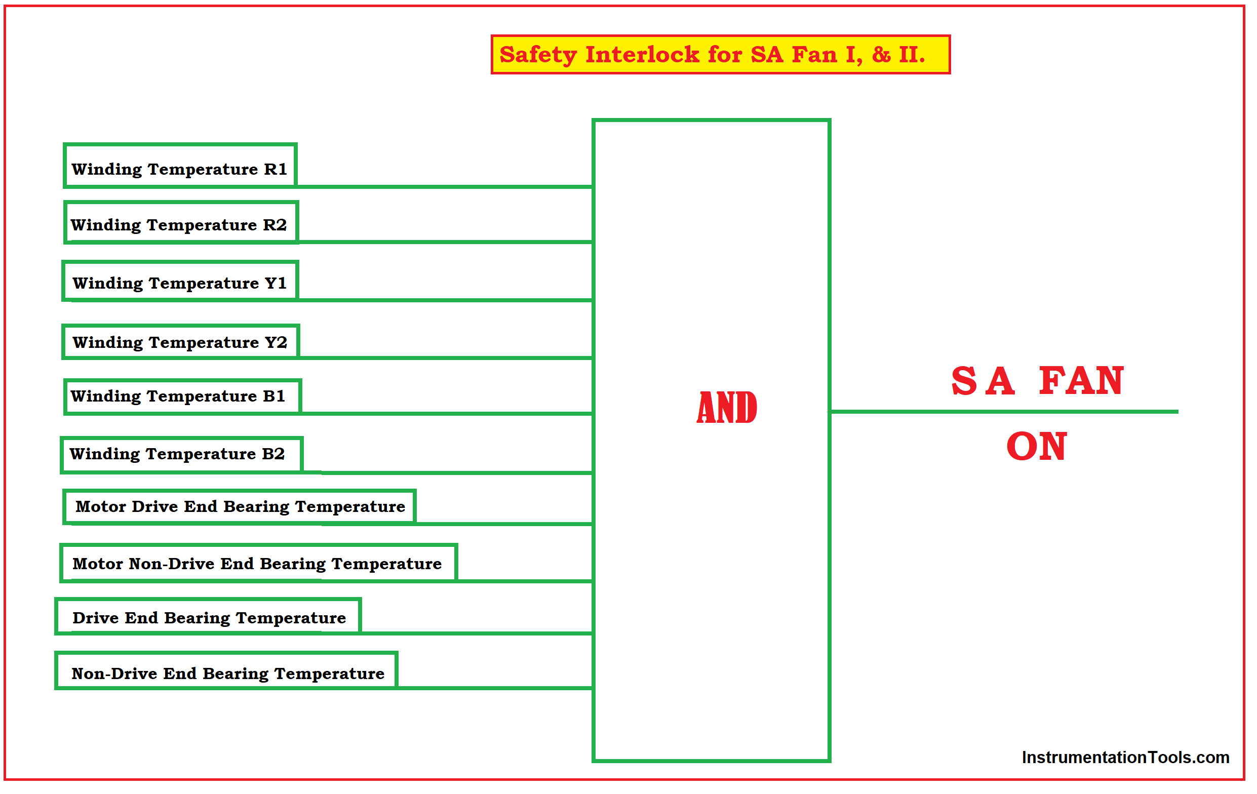
Safety Interlock for S.A Fan I, & II.
- Winding Temperature R1
- Winding Temperature R2
- Winding Temperature Y1
- Winding Temperature Y2
- Winding Temperature B1
- Winding Temperature B2
- Motor Drive End Bearing Temperature
- Motor Non-Drive End Bearing Temperature
- Drive End Bearing Temperature
- Non-Drive End Bearing Temperature
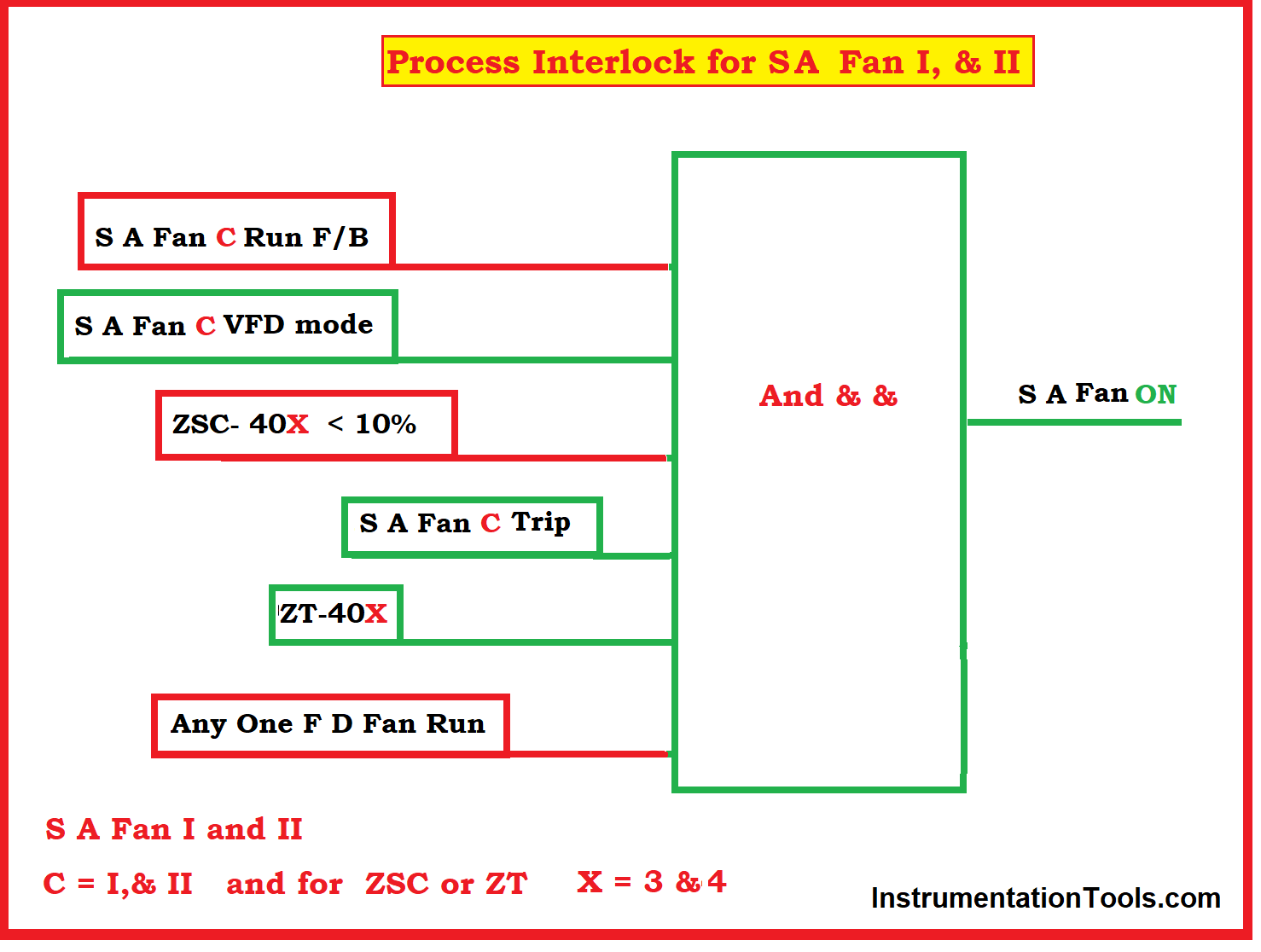
Process Interlocks for SA Fan I, & II.
- SA Fan-C Run Feedback
- SA Fan-I VFD mode
- ZSC- 40X
- ZT-40X
- SA –Fan C Trip
C = I,& II and for ZSC or ZT X = 3 & 4 SA Fan I and II


Very nicely illustrated thanks for the sharing