Inst ToolsInst ToolsInst Tools
  • Courses
  • Automation
    • PLC
    • Control System
    • Safety System
    • Communication
    • Fire & Gas System
  • Instrumentation
    • Design
    • Pressure
    • Temperature
    • Flow
    • Level
    • Vibration
    • Analyzer
    • Control Valve
    • Switch
    • Calibration
    • Erection & Commissioning
  • Interview
    • Instrumentation
    • Electrical
    • Electronics
    • Practical
  • Q&A
    • Instrumentation
    • Control System
    • Electrical
    • Electronics
    • Analog Electronics
    • Digital Electronics
    • Power Electronics
    • Microprocessor
  • Request
Search
  • Books
  • Software
  • Projects
  • Process
  • Tools
  • Basics
  • Formula
  • Power Plant
  • Root Cause Analysis
  • Electrical Basics
  • Animation
  • Standards
  • 4-20 mA Course
  • Siemens PLC Course
Reading: Basics of DP Transmitter Suppression and Elevation
Share
Font ResizerAa
Inst ToolsInst Tools
Font ResizerAa
  • Courses
  • Design
  • PLC
  • Interview
  • Control System
Search
  • Courses
  • Automation
    • PLC
    • Control System
    • Safety System
    • Communication
    • Fire & Gas System
  • Instrumentation
    • Design
    • Pressure
    • Temperature
    • Flow
    • Level
    • Vibration
    • Analyzer
    • Control Valve
    • Switch
    • Calibration
    • Erection & Commissioning
  • Interview
    • Instrumentation
    • Electrical
    • Electronics
    • Practical
  • Q&A
    • Instrumentation
    • Control System
    • Electrical
    • Electronics
    • Analog Electronics
    • Digital Electronics
    • Power Electronics
    • Microprocessor
  • Request
Follow US
All rights reserved. Reproduction in whole or in part without written permission is prohibited.
Inst Tools > Blog > Level Measurement > Basics of DP Transmitter Suppression and Elevation

Basics of DP Transmitter Suppression and Elevation

Last updated: December 30, 2018 11:18 am
Editorial Staff
Level Measurement
4 Comments
Share
6 Min Read
SHARE

Transmitter Suppression and Elevation

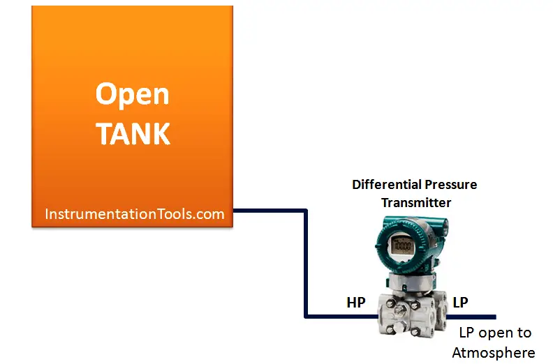
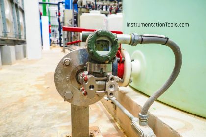
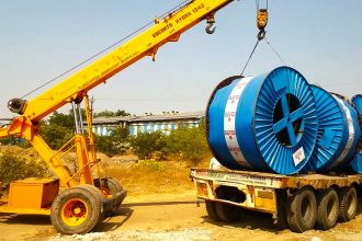
A very common scenario for liquid level measurement is where the pressure-sensing instrument is not located/installed at the same level as the 0% measurement point. The following photograph shows an example of this, where a differential pressure transmitter is being used to sense hydrostatic pressure of water inside a tank:

Differential Pressure Transmitter Zero Suppression

Consider the below example of a pressure sensor measuring the level of liquid ethanol in a storage tank. The measurement range for liquid height in this ethanol storage tank is 0 to 40 feet, but the transmitter is located 30 feet below the tank:

Hydrostatic Pressure Measurement

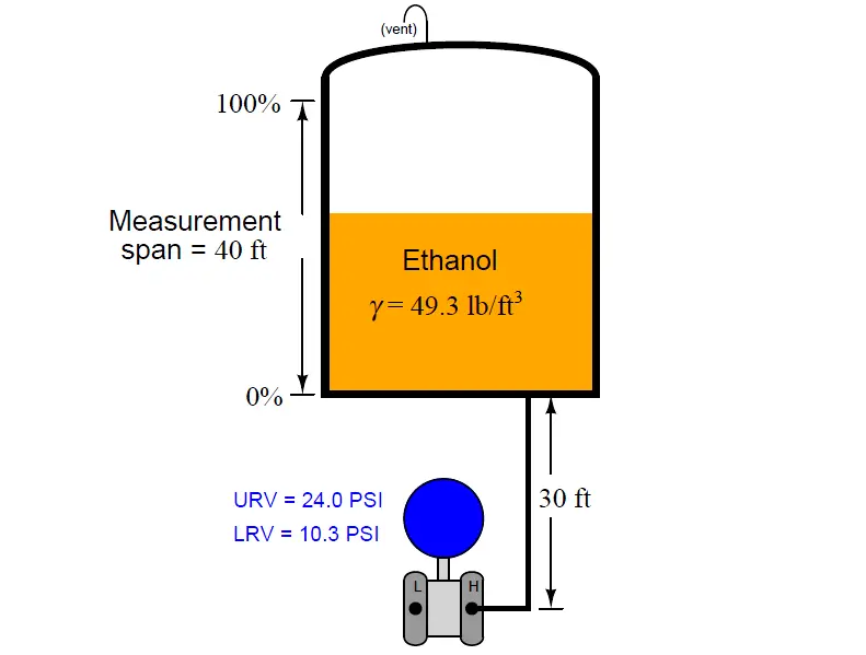
Note : A Vent is connected at the Top of the tank, so if any gas or pressure exists above the liquid in the tank will be vented out.

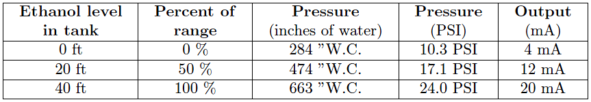
This means the transmitter’s impulse line contains a 30-foot elevation head of ethanol, so the transmitter “sees” 30 feet of ethanol when the tank is empty and 70 feet of ethanol when the tank is full. When there is no ethanol in the tank, pressure transmitter senses 10.3 psi (assumed) because it installed the tapping point and this causes extra pressure on the transmitter. as  A 3-point calibration table for this instrument would look like this, assuming a 4 to 20 mA DC output signal range:

Hydrostatic Pressure Measurement Calculations

Another common scenario is where the transmitter is mounted at or near the vessel’s bottom, but the desired level measurement range does not extend to the vessel bottom:

Level Transmitter Mounted below the tapping point

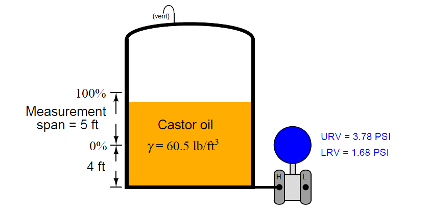
In this example, the transmitter is mounted exactly at the same level as the vessel bottom, but the level measurement range begins at 4 feet up from the vessel bottom. At the level of castor oil deemed 0%, the transmitter “sees” a hydrostatic pressure of 1.68 PSI (46.5 inches of water column) and at the 100% castor oil level the transmitter “sees” a pressure of 3.78 PSI (105 inches water column). Thus, these two pressure values would define the transmitter’s lower and upper range values (LRV and URV), respectively.

The term for describing either of the previous scenarios, where the lower range value (LRV) of the transmitter’s calibration is a positive number, is called zero suppression. If the zero offset is reversed (e.g. the transmitter mounted at a location higher than the 0% process level), it is referred to as zero elevation.

If the transmitter is elevated above the process connection point, it will most likely “see” a negative pressure (vacuum) with an empty vessel owing to the pull of liquid in the line leading down from the instrument to the vessel. It is vitally important in elevated transmitter installations to use a remote seal rather than an open impulse line, so liquid cannot dribble out of this line and into the vessel:

Note : As you are about to see, the calibration of an elevated transmitter depends on us knowing how much hydrostatic pressure (or vacuum, in this case) is generated within the tube connecting the transmitter to the process vessel. If liquid were to ever escape from this tube, the hydrostatic pressure would be unpredictable, and so would be the accuracy of our transmitter as a level-measuring instrument. A remote seal diaphragm guarantees no fill fluid will be lost if and when the process vessel goes empty.

Remote Seal Transmitter installed above tapping point

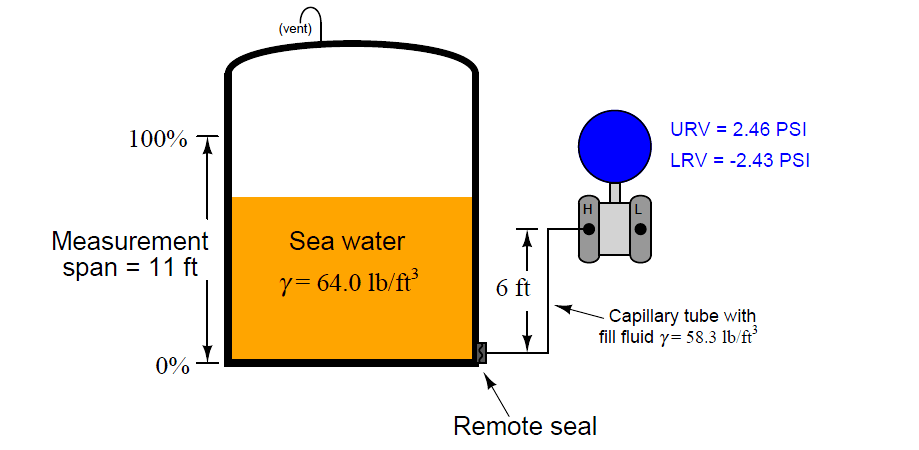
In this example, we see a remote seal system with a fill fluid having a density of 58.3 lb/ft3, and a process level measurement range of 0 to 11 feet of sea water (density = 64 lb/ft3). The transmitter elevation is 6 feet, which means it will “see” a vacuum of −2.43 PSI (−67.2 inches of water column) when the vessel is completely empty. This, of course, will be the transmitter’s calibrated lower range value (LRV). The upper range value (URV) will be the pressure “seen” with 11 feet of sea water in the vessel. This much sea water will contribute an additional 4.89 PSI of hydrostatic pressure at the level of the remote seal diaphragm, causing the transmitter to experience a pressure of +2.46 PSI.

Note : The sea water’s positive pressure at the remote seal diaphragm adds to the negative pressure already generated by the downward length of the capillary tube’s fill fluid (−2.43 PSI), which explains why the transmitter only “sees” 2.46 PSI of pressure at the 100% full mark.

Also Read : Remote Seal Transmitters Range Calculations

Credits : by Tony R. Kuphaldt – Creative Commons Attribution 4.0 License

Don't Miss Our Updates
Be the first to get exclusive content straight to your email.
We promise not to spam you. You can unsubscribe at any time.
Invalid email address
You've successfully subscribed !

Continue Reading

Open and Closed Tank Level Calculations
Radar and Ultrasonic Level Transmitter Practical Problems Troubleshooting
Radiometric level measurement Working Principle
Magnetostrictive Tank Gauging (MTG)
Microwave Barrier Level Switch Working Principle
Radiation Level Measurement
Share This Article
Facebook Whatsapp Whatsapp LinkedIn Copy Link
Share
4 Comments
  • JAYANTA MUKHERJEE says:
    July 28, 2018 at 9:11 am

    what is zero elevation concept in tank level measurement in D.P. transmitter nozzle flapper system in marine field ? 4 marks

    sorry to say , but not get any simplified form of answer in your study materials .

    Reply
  • wayne says:
    October 31, 2020 at 12:44 am

    how do you calculate URV when you have a 9-11 psi nitrogen blanket on top of the tank level?

    Reply
  • wayne says:
    October 31, 2020 at 12:46 am

    the transmitter is 30″ below the tank straight wall. We will probably put 30″ for the LRV to start our level at the tank straight wall.

    Reply
  • rowell says:
    March 5, 2023 at 11:30 am

    what is the formula of DP Transmitter Suppression and Elevation

    Reply

Leave a Reply Cancel reply

Your email address will not be published. Required fields are marked *

Stay Connected

128.3kFollowersLike
69.1kFollowersFollow
210kSubscribersSubscribe
38kFollowersFollow

Categories

Explore More

Effect of Temperature & Pressure on Level Measurement
Level Measurement Objective Questions
Purpose of Tank Gauging Level Measurement
Ultrasonic Level Switch Working Principle
Vibrating Fork Level Switch Working Animation
What is the Simple Alternative Vessel Level Indication?
Float level switch Principle
Installation and Calibration of Level Transmitter

Keep Learning

Float Level Measurement

Types of Level Measurement

Magnetic Float Level Sensor Principle

Magnetic Float Level Transmitter Working Principle

DP Transmitter Capillary arrangement

DP Transmitter Interface Level Measurement Principle, Limitations, Selection, Installation, Design & Calibration

Conductive Level Measurement Working Principle

Conductive Level Measurement Working Principle

Interface level Measurement

Interface Level Measurement using DP Transmitter

Level Sensors MCQ

Level Sensors MCQ – Industrial Instrumentation

Magnetostrictive Level Transmitter Calibration

Magnetostrictive Level Transmitter Calibration Procedure

Density Calculation​ Using DP Transmitter

How to Measure Density using DP Transmitter?

Learn More

Automatic Box Filling System using PLC Programming

Automatic Box Filling System using PLC Programming

Instrument Air Quality

Instrument Air Quality

Addressable Fire Alarm System

Which One is Best – Conventional or Addressable Fire Alarm System?

surface-mounted water pump

Surface-mounted Water Pump

ESP8266 WiFi Module Projects

ESP8266 WiFi Module Projects for Engineering Students

Thermocouple Voltage Curves

What are the Thermocouple Applications?

Power Electronics Objective Questions

Thyristors Quiz

pi filter Operation

pi filter Operation

Menu

  • About
  • Privacy Policy
  • Copyright

Quick Links

  • Learn PLC
  • Helping Hand
  • Part Time Job

YouTube Subscribe

Follow US
All rights reserved. Reproduction in whole or in part without written permission is prohibited.
Welcome Back!

Sign in to your account

Username or Email Address
Password

Lost your password?