This article discusses the PLC program Batch Mixing system with looping using CX-Programmer. The system can only be started if the “Set Value” Loop has been Set.
Automate Batch Mixing with Repeated Cycles
This PLC system Runs automatically, when the system is started, the Input Valve will OPEN until a certain time limit to fill the Mixer tank with liquid.
After the Input Valve has CLOSED, the Mixer will be ON until a certain time limit to perform the liquid Mixing process. When the mixing process is complete, the Output Valve will open within the same time limit to empty liquid from the mixer tank.
The system will run again as many times as the “Set Value” of the Loop has been Set.
How The PLC Program Works?
This program only uses 2 buttons, the START_SYSTEM (0.00) button is used to Turn On the system, and the STOP_SYSTEM (0.01) button is used to Turn Off the system.
Before the system is started, the “Set value” in the memory word SV_LOOP (D1) must be Set. The memory word SV_LOOP (D1) is used as a limit on the number of times the system is Run. For example, if the memory word SV_LOOP (D1) is set to “3”, the system will be run 3 times.
When the START_SYSTEM (0.00) button is pressed, the Output VALVE_INPUT (100.00) will OPEN for 10 seconds to carry out the liquid filling process in the Mixer tank. The Output VALVE_INPUT (100.00) will CLOSE when timer TIMER_1 (T0000) has reached the “Set value”.
When timer TIMER_1 (T0000) has finished counting, the Output MIXER (100.01) will be ON for 15 seconds to carry out the Mixing process in the Mixer tank. The Output MIXER (100.01) will be OFF when timer TIMER_2 (T0001) has reached the “Set value”.
When timer TIMER_1 (T0001) has finished counting, the Output VALVE_OUTPUT (100.02) will OPEN for 10 seconds to empty the Mixer tank. The Output VALVE_OUTPUT (100.02) will CLOSE when timer TIMER_3 (T0002) has reached the “Set value”.
This program sequence will be executed again as many times as the value has been Set in the memory word SV_LOOP (D1). When the program has Run as much as the value in the memory word SV_LOOP (D1), memory bit LOOP_CUTOFF (W0.01) will be ON to Stop the system.
I/O List
| Comment | Input (I) | Output (Q) | Memory Word | Memory Bits | Timer |
| START_SYSTEM | 0.00 | ||||
| STOP_SYSTEM | 0.01 | ||||
| VALVE_INPUT | 100.00 | ||||
| MIXER | 100.01 | ||||
| VALVE_OUTPUT | 100.02 | ||||
| TIMER_1 | T0000 | ||||
| TIMER_2 | T0001 | ||||
| TIMER_3 | T0002 | ||||
| SYSTEM_ON | W0.00 | ||||
| LOOP_CUTOFF | W0.01 | ||||
| PV_LOOP | D0 | ||||
| SV_LOOP | D1 |
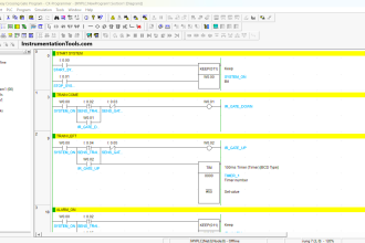
Omron PLC Code
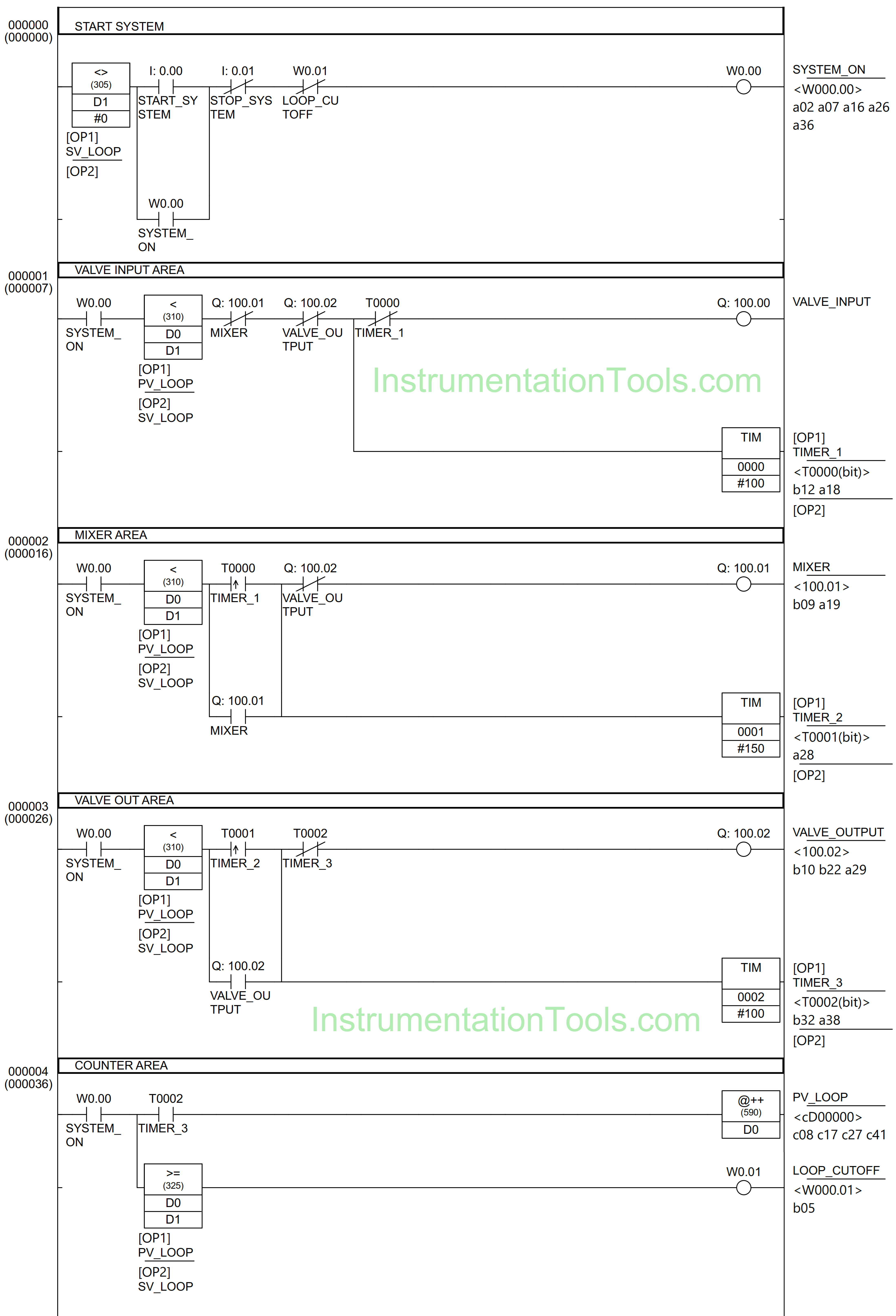
RUNG 0 (START SYSTEM)
In this Rung, the memory bit SYSTEM_ON (W0.00) will be ON when the memory word SV_LOOP (D1) has a value not equal to zero “0” and the START_SYSTEM (0.00) button is Pressed. Because it uses Latching, memory bit SYSTEM_ON (W0.00) remains ON even though START_SYSTEM (0.00) button has been Released.
The memory bit SYSTEM_ON (W0.00) will be OFF if the STOP_SYSTEM (0.01) button is Pressed or when NC contact of the memory bit LOOP_CUTOFF (W0.01) is in the HIGH state.
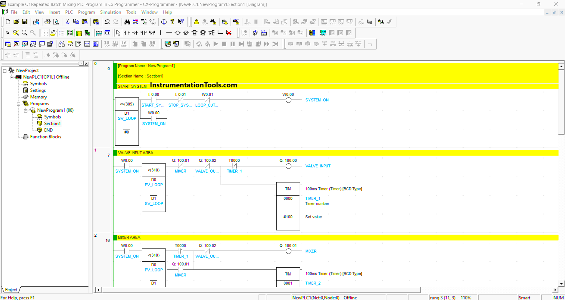
RUNG 1 (VALVE INPUT AREA)
In this Rung, when NO contact of the memory bit SYSTEM_ON (W0.00) in a HIGH state and the value in the memory word PV_LOOP (D0) is less than SV_LOOP (D1), then Output VALVE_INPUT (100.00) will OPEN and timer TIMER_1 (T0000) starts count.
The Output VALVE_INPUT (100.00) will be CLOSE when one of the NC contacts of TIMER_1 (T0000), MIXER (100.01), and VALVE_OUTPUT (100.02) in the HIGH state.
RUNG 2 (MIXER AREA)
When NO contacts of the memory bits SYSTEM_ON (W0.00) and TIMER_1 (T0000) in a HIGH state and the value in the memory word PV_LOOP (D0) is less than SV_LOOP (D1), then the Output MIXER (100.01) will be ON and timer TIMER_2 (T0001) start counting.
The Output MIXER (100.01) will be OFF when the NC contact of VALVE_OUTPUT (100.02) is in the HIGH state.
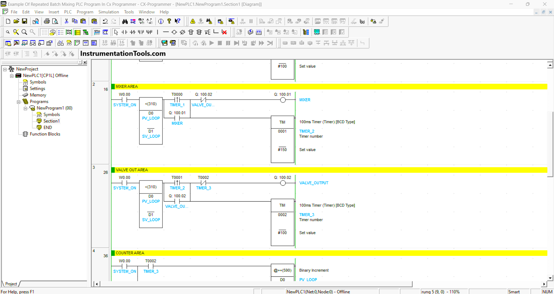
RUNG 3 (VALVE OUT AREA)
When NO contacts of the memory bits SYSTEM_ON (W0.00) and TIMER_2 (T0001) in a HIGH state and the value in the memory word PV_LOOP (D0) is less than SV_LOOP (D1), then the Output VALVE_OUTPUT (100.02) will OPEN and timer TIMER_3 (T0002) starts count.
The Output VALVE_OUTPUT (100.02) will be CLOSE when the NC contact of TIMER_3 (T0002) is HIGH.
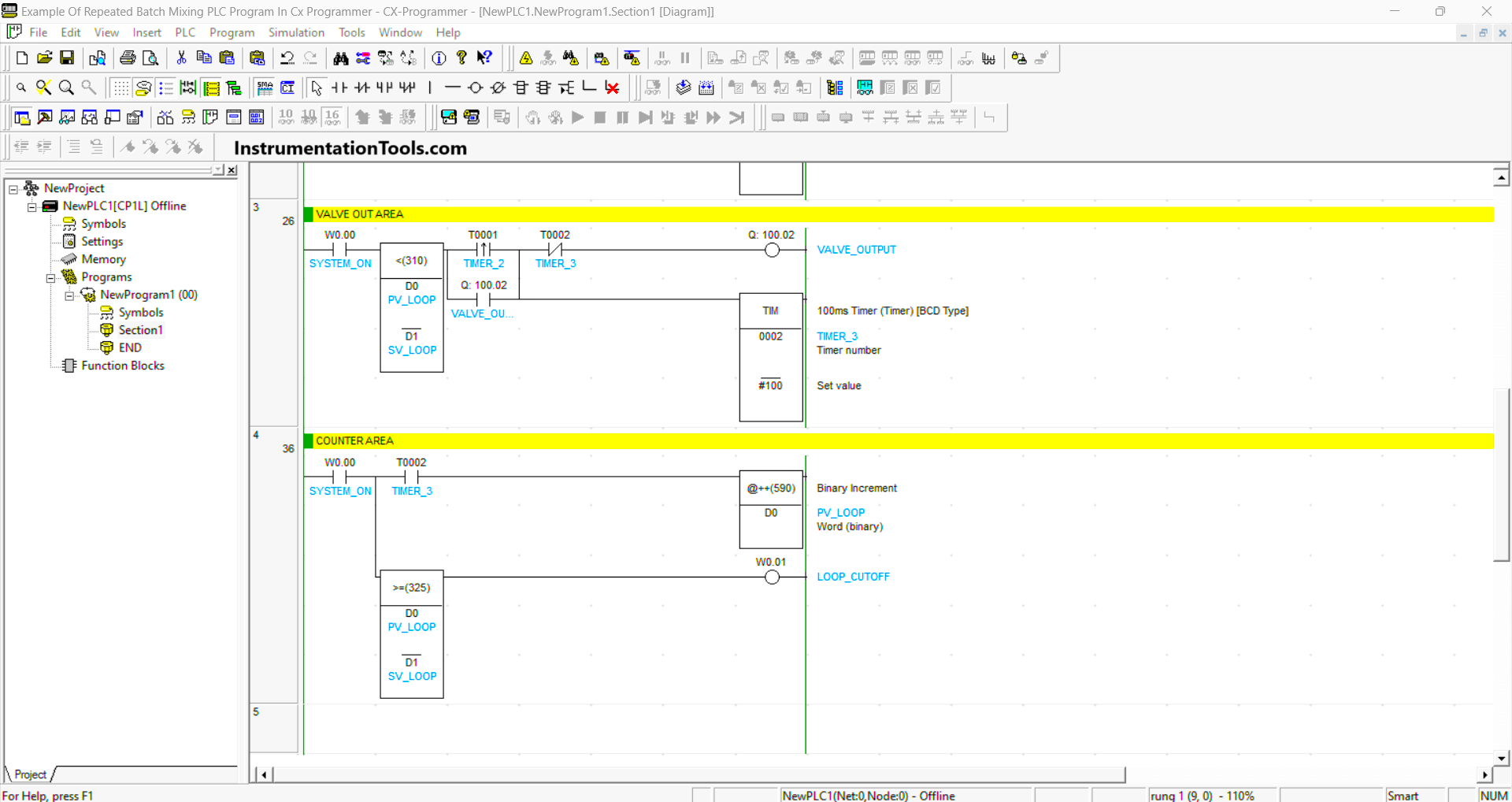
RUNG 4 (COUNTER AREA)
In this Rung, when NO contact of the memory bit SYSTEM_ON (W0.00) and TIMER_3( T0002) in the HIGH state, the value in the memory word PV_LOOP (D0) will increase (+1).
The memory bit LOOP_CUTOFF (W0.01) will be ON when the value in the memory word PV_LOOP (D0) is greater than or equal to SV_LOOP (D1) and NO contact of the memory bit SYSTEM_ON (W0.00) in the HIGH state.
Read Next:
- PLC Product Sticker Machine with Weighing
- Automatic Exhaust Fan XG5000 PLC Program
- Automatic Highway Lights Program in PLC
- Waste-Burning System OMRON PLC Logic
- Water Pump PLC Program CX-Programmer