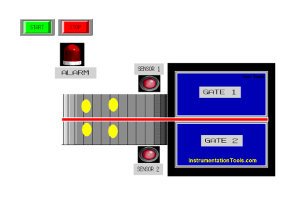
The Worker Attendance System generally uses an ID Card device to identify workers who will enter the office area. If the database from the ID Card device finds a match in the worker’s data, Face ID will send a signal to the Gate so that the Gate Opens to allow the worker to enter the office.
When the worker has passed the gate, the system will record it and then the gate will Close again. When workers leave the office area, the same procedure will be carried out and data on workers who are still in the office area will be updated.
Attendance System
This PLC program has 3 buttons, the START_SYSTEM (0.00) button is used to Turn On the system, the STOP_SYSTEM (0.01) button is used to Turn Off the system, and the RESET_COUNTER (0.06) button is used to Reset the COUNTER (D0) data to zero value “0”.
Worker Login System
When the Input CARD_ID_IN_TRIGGER (0.02) is in a HIGH state, the GATE_IN_OPEN (100.00) Output will be ON and allow workers to enter the office area. When the SENS_WORKER_IN (0.03) sensor detects that the worker has passed the Gate, the GATE_IN_OPEN Output (100.00) will be OFF.
If within 10 seconds after the Input CARD_ID_IN_TRIGGER (0.02) in HIGH state and the SENS_WORKER_IN (0.03) sensor does not detect a worker passing through the Gate, then the GATE_IN_OPEN Output (100.00) will be OFF.
When the SENS_WORKER_IN (0.03) sensor is in a HIGH state, the data in memory word COUNTER (D0) will increase (+1).
Worker Exit System
When the Input CARD_ID_OUT_TRIGGER (0.04) is in a HIGH state, the GATE_OUT_OPEN (100.02) Output will be ON and allow workers to leave the office area. When the SENS_WORKER_OUT (0.05) sensor detects that the worker has passed the Gate, the GATE_OUT_OPEN (100.02) Output will be OFF.
If within 10 seconds after the Input CARD_ID_OUT_TRIGGER (0.04) in HIGH state and the SENS_WORKER_OUT (0.05) sensor does not detect a worker passing through the Gate, then the GATE_OUT_OPEN (100.02) Output will be OFF.
When the SENS_WORKER_OUT (0.05) sensor is in the HIGH state, the data in memory word COUNTER (D0) will decrease (-1).
Inputs and Outputs
| Comment | Input (I) | Output(Q) | TIMER | Word Memory | Memory Bits |
| START_SYSTEM | 0.00 | ||||
| STOP_SYSTEM | 0.01 | ||||
| CARD_ID_IN_TRIGGER | 0.02 | ||||
| SENS_WORKER_IN | 0.03 | ||||
| CARD_ID_OUT_TRIGGER | 0.04 | ||||
| SENS_WORKER_OUT | 0.05 | ||||
| RESET_COUNTER | 0.06 | ||||
| GATE_IN_OPEN | 100.00 | ||||
| GATE_IN_CLOSE | 100.01 | ||||
| GATE_OUT_OPEN | 100.02 | ||||
| GATE_OUT_CLOSE | 100.03 | ||||
| TIMER_1 | T0000 | ||||
| TIMER_2 | T0001 | ||||
| SYSTEM_ON | W0.00 | ||||
| COUNTER | D0 |
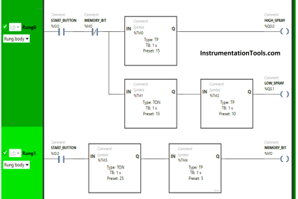
PLC Program using CX-Programmer
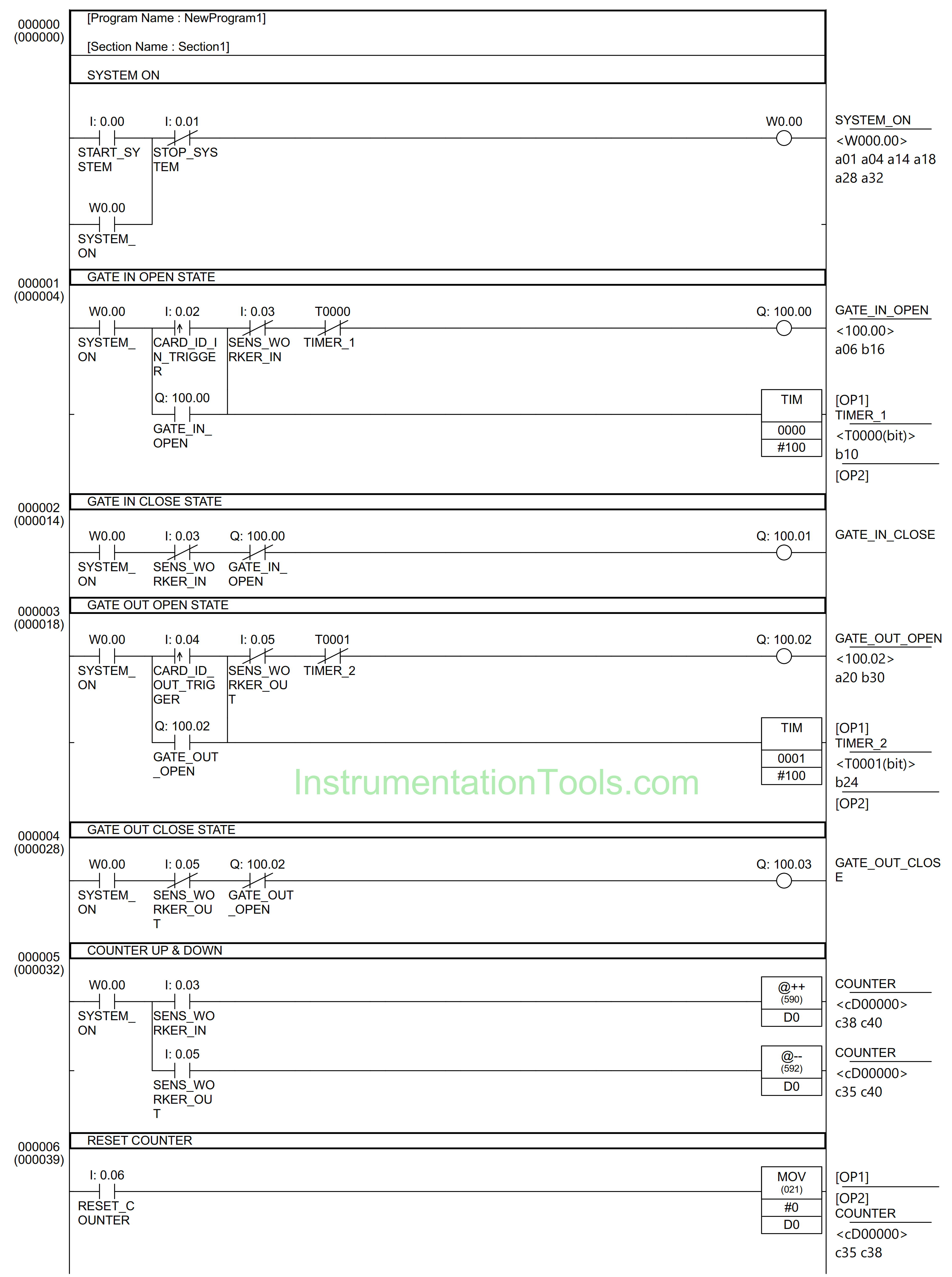
RUNG 0 (SYSTEM ON)
In this Rung, when the START_SYSTEM (0.00) button is pressed, the memory bit SYSTEM_ON (W0.00) changes to the HIGH state. Because it uses Latching, the memory bit SYSTEM_ON (W0.00) remains in the HIGH state even though the START_SYSTEM (0.00) button has been Released.
The memory bit SYSTEM_ON (W0.00) will change to a LOW state if the STOP_SYSTEM (0.01) button is Pressed.
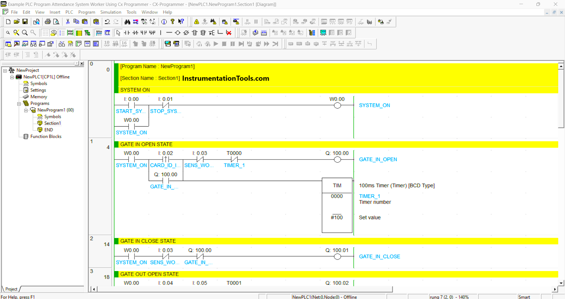
RUNG 1 (GATE IN OPEN STATE)
When the memory bit SYSTEM_ON (W0.00) and Input from CARD_ID_IN_TRIGGER (0.02) are in the HIGH state, then the GATE_IN_OPEN (100.00) Output will be ON and Timer TIMER_1 (T0000) starts counting up to 10 seconds.
The GATE_IN_OPEN (100.00) Output will be OFF when the NC contact of sensor SENS_WORKER_IN (0.03) or timer TIMER_1 (T0000) is in the HIGH state.
RUNG 2 (GATE IN CLOSE STATE)
When the memory bit SYSTEM_ON (W0.00) is in the HIGH state, the Output GATE_IN_CLOSE (100.01) will be ON.
The GATE_IN_CLOSE (100.01) Output will be OFF when the NC contact of sensor SENS_WORKER_IN (0.03) or GATE_IN_OPEN (100.00) Output in the HIGH state.
RUNG 3 (GATE OUT OPEN STATE)
When the memory bit SYSTEM_ON (W0.00) and the CARD_ID_OUT_TRIGGER (0.04) Input are in a HIGH state, the GATE_OUT_OPEN (100.02) Output will be ON and Timer TIMER_2 (T0001) will start counting up to 10 seconds.
The GATE_OUT_OPEN (100.02) Output will be OFF when the NC contact of sensor SENS_WORKER_OUT (0.05) or timer TIMER_2 (T0001) is in the HIGH state.
RUNG 4 (GATE OUT CLOSE STATE)
When the memory bit SYSTEM_ON (W0.00) is in the HIGH state, the Output GATE_OUT_CLOSE (100.03) will be ON.
The GATE_OUT_CLOSE (100.03) Output will be OFF when the NC contact of Input of CARD_ID_OUT_TRIGGER (0.04) or the Output of GATE_OUT_OPEN (100.02) in the HIGH state.
RUNG 5 (COUNTER UP & DOWN)
In this Rung, when the memory bit SYSTEM_ON (W0.00) and the NO contact from SENS_WORKER_IN (0.03) sensor are in the HIGH state, the data in memory word COUNTER (D0) will increase (+1) because it uses the Increment instruction.
But when the memory bit SYSTEM_ON (W0.00) and the NO contact from SENS_WORKER_OUT (0.05) sensor are in the HIGH state, the data in memory word COUNTER (D0) will decrease (-1) because it uses the Decrement instruction.
RUNG 6 (RESET COUNTER)
When the NO contact of RESET_COUNTER (0.06) button is pressed, the data in memory word COUNTER (D0) will become zero “0” because the MOV instruction moves zero value “0” to memory word COUNTER (D0).
Read Next:
- Sanitizer Complex Ladder Logic PLC Example
- Door Locking System PLC Application Example
- CX-Programmer Products Sorting & Counting
- Real-Time Clock in Omron CX Programmer
- PLC Program for Ceramic Burning Oven