To study the working of Allen Bradley Math functions (ADD, SUB, MUL, DIV, SQR & NEG) using simple example in programmable logical controllers (PLC).
Allen Bradley Math Functions
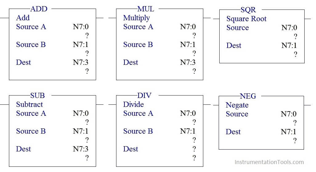
There are three parameters in each block,
Source A –Address of the first Value
Source B –Address of the second value
Destination (Dest) – Address where result of the function will store.
PLC Math Functions
ADD:
Add block is used to do the Addition of the two values stored in source A and source B and store the output in destination address.
SUB:
Sub block is used to do the Subtraction of the two values stored in source A and source B and store the output in destination address.
MUL:
MUL block is used to do the Multiplication of the two values stored in source A and source B and store the output in destination address.
DIV:
DIV block is used to do the Division of the two values stored in source A and source B and store the output in destination address.
SQR
SQR block is used to find the square root of the value stored in source address and results the value in destination address.
NEQ:
NEQ block is used to negate the value stored in source address and results the value in destination.
Program Logic
When start switch is pressed,
- Value stored in N7:0 and N7:1 gets added and results the value in N7:2
- Add block output is one of the input to Sub block which do subtraction function by taking value stored in N7:1 and stores the address in N7:3.
- Sub block output is one the input to Mul block and perform multiplication along with value stored in N7:1 and stores the result in N7:4
- Mul block output is one the input to DIV block and perform Division along with value stored in N7:0 and stores the result in N7:5
- SQR block performs square root of the Value stored in N7:5 and results the output in N7:6.
- Value stored in N7:6 get negated using NEG block and results the final output in N7:7.
- If the resulted output is positive turn on output positive indication else output negative indication.
PLC Program using Math Functions
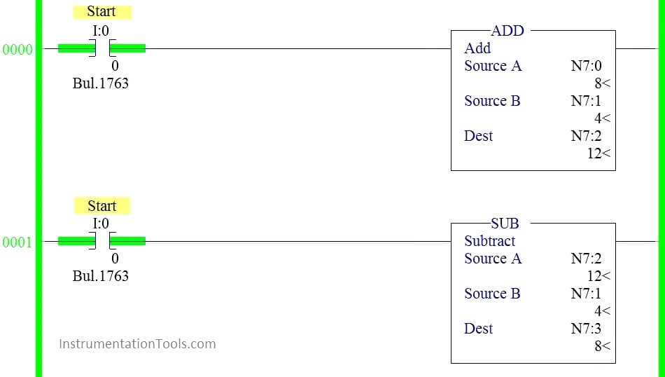
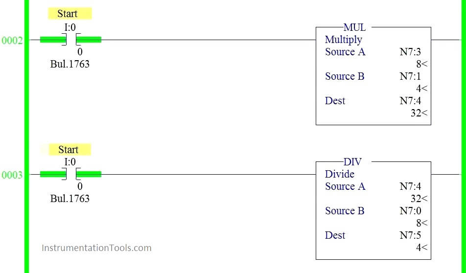
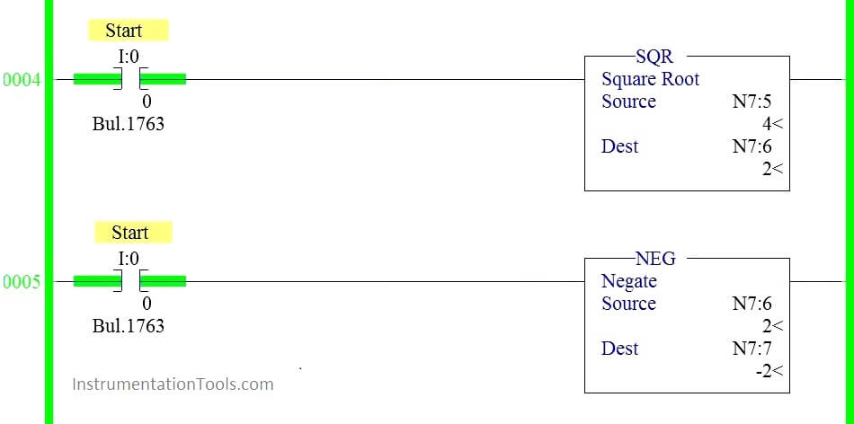
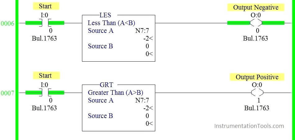
Ladder Logic Description:
RUNG 0000:
When Start switch is pressed, N7:0 and N7:1 get added and store the value in N7:2.
RUNG 0001:
Value stored in N7:2 get subtracted with value stored in N7:1 and results the value in N7:3.
RUNG 0002:
Value stored in N7:3 get multiplied with value stored in N7:1 and results the value in N7:4.
RUNG 0003:
Value stored in N7:4 get divided by value stored in N7:0 and results the value in N7:5.
RUNG 0004:
Value stored in N7:5 get squared and results the value in N7:6.
RUNG 0005:
Value stored in N7:6 get negated and results the value in N7:7.
RUNG 0006:
Less than block (Source B value sets to 0) is used to check whether the result is negative and results the output in indication lamp (O: 0/0)
RUNG 0007:
Greater than block (Source B value sets to 0) is used to check whether the result is positive and results the output in indication lamp (O: 0/1)
Conclusion:
We can use this example program to understand the working Math block functions in AB PLC.
If you liked this article, then please subscribe to our YouTube Channel for PLC and SCADA video tutorials.
You can also follow us on Facebook and Twitter to receive daily updates.
Read Next:
Single Push button Ladder Logic
Masked Move Instruction in PLC
